Technical Guide P92x/EN TD/E11
Technical Data
MiCOM P921-P922-P923 Page 7/30
1.4 Logic inputs
All the logic inputs are optically-isolated and independent : the MiCOM P921 relay
has 2 logic inputs and the MiCOM P922-P923 relays have 5 logic inputs.
Energization of the logic inputs is realised with a DC or AC auxiliary voltage.
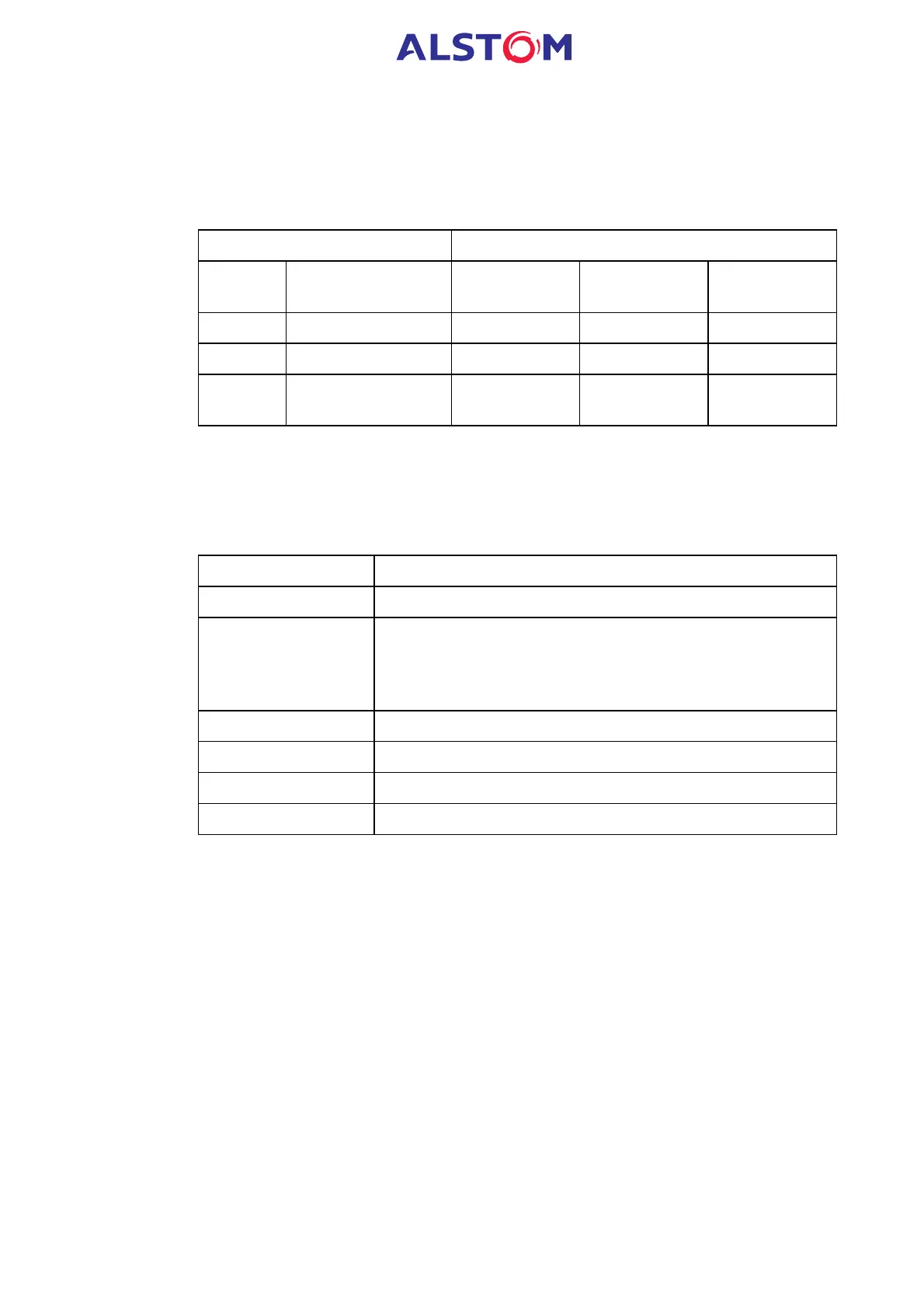
Logical « ON »
CORTEC
code
Auxiliary voltage :
nominal ranges
Voltage range
Minimum
voltage
Minimum
current (mA)
A 24-60Vdc 19 – 60 Vdc 15 Vdc 3,35 mA
F 48-150Vdc 32 – 150 Vdc 25 Vdc 3,35 mA
M 130-250Vdc /
100-250Vac
48 – 250 Vdc 38 Vdc 2,20 mA
Logic input recognition time = 5 ms
1.5 Output Relay Contacts
The output contacts of the MiCOM P921-P922-P923 relays are AgCdO dry contacts.
Their technical characteristics are indicated below :
Make and carry : 30A for 3s
Carry : 5A continuous
Break : DC : 50W resistive
DC : 25W inductive (L/R = 40ms)
AC : 1250VA
AC : 1250 VA inductive (cos j = 0.5)
Maxima : 5A and 300V
Loaded contact : 10 000 operation minimum
Unloaded contact : 100 000 operation minimum
Operation time < 7 ms