Technical Guide P92x/EN TD/E11
Technical Data
MiCOM P921-P922-P923 Page 11/30
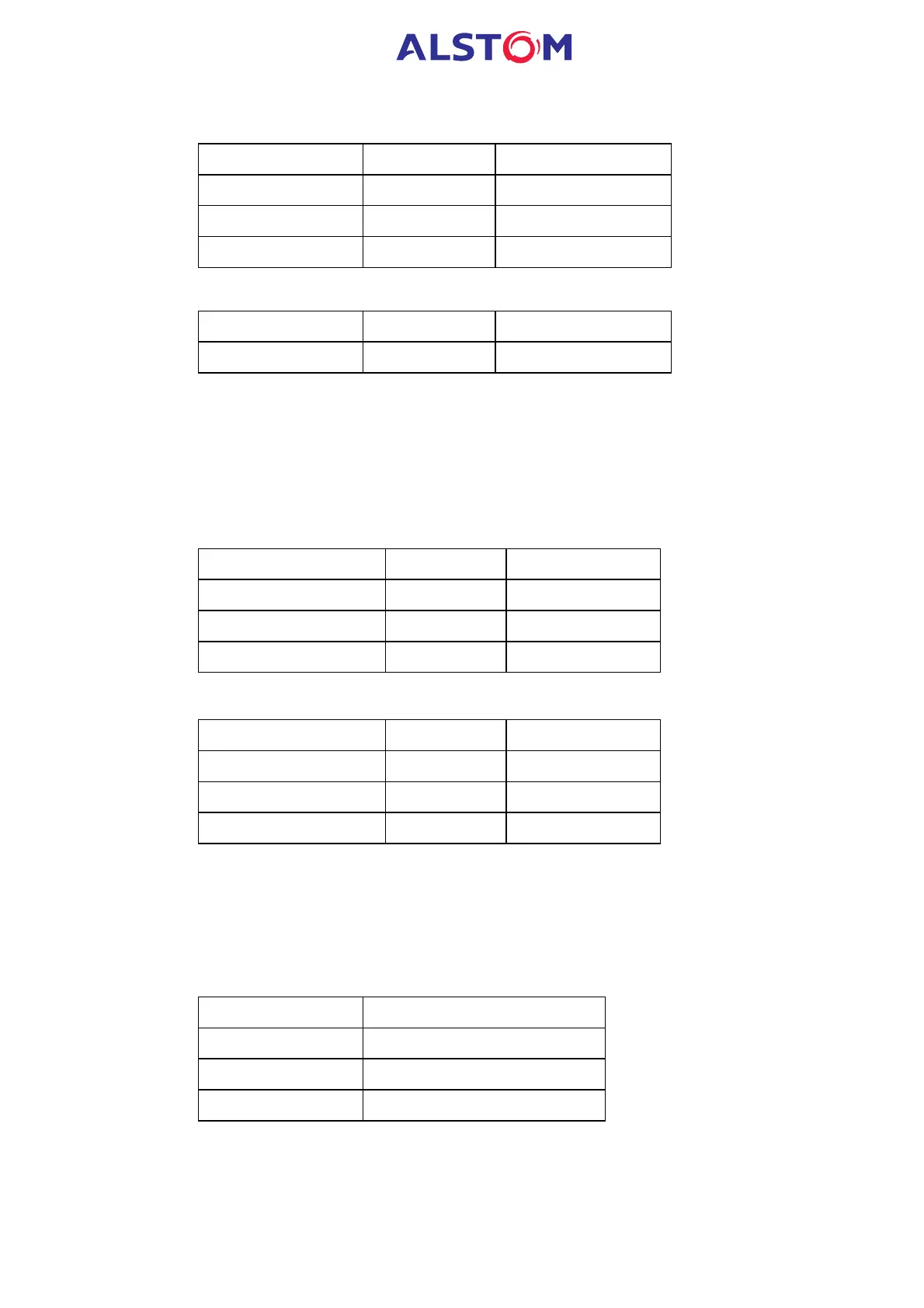
3.1.4 Definite time delay characteristics
Setting Range Step Size
tV< 0 – 599s 0.01s
tV<< 0 – 599s 0.01s
tV<<< 0 – 599s 0.01s
3.1.5 Hysteresis
Setting Range Step Size
Hysteresis 1.02 – 1.05 0.01s
NOTE : this range is a percentage value of the pickup value of the
undervoltage elements (see paragraph 9.3 Protection accuracy)
3.2 Overvoltage (ANSI code 59)
3.2.1 Threshold settings (secondary values)
- Nominal voltage range : 57 – 130V
Setting Range Step Size
V>= Voltage Set 5 – 200V 0.1V
V>>= Voltage Set 5 – 260V 0.1V
V>>>= Voltage Set 5 – 260V 0.1V
- Nominal voltage range : 220 – 480V
Setting Range Step Size
V>= Voltage Set 20 – 720V 0.5V
V>>= Voltage Set 20 – 960V 0.5V
V>>>= Voltage Set 20 – 960V 0.5V
3.2.2 Time delay settings
Each voltage element is associated to an independent time delay.
Each measuring element time delay can be blocked by the operation of a user
defined logic (optical isolated) input (see “Blocking logic1” or “Blocking logic2”
functions).
Element Time delay type
1
st
stage Definite Time (DT) or IDMT
2
nd
stage DT
3
rd
stage DT