Technical Guide P92x/EN TD/E11
Technical Data
MiCOM P921-P922-P923 Page 21/30
4. MEASUREMENT AND RECORDS
4.1 Settings
The measured values are displayed on the LCD of the relay ; they are true RMS
values (up to the 10
th
harmonic) and are primary values.
They can also be read through the communication ports (RS232 or RS485).
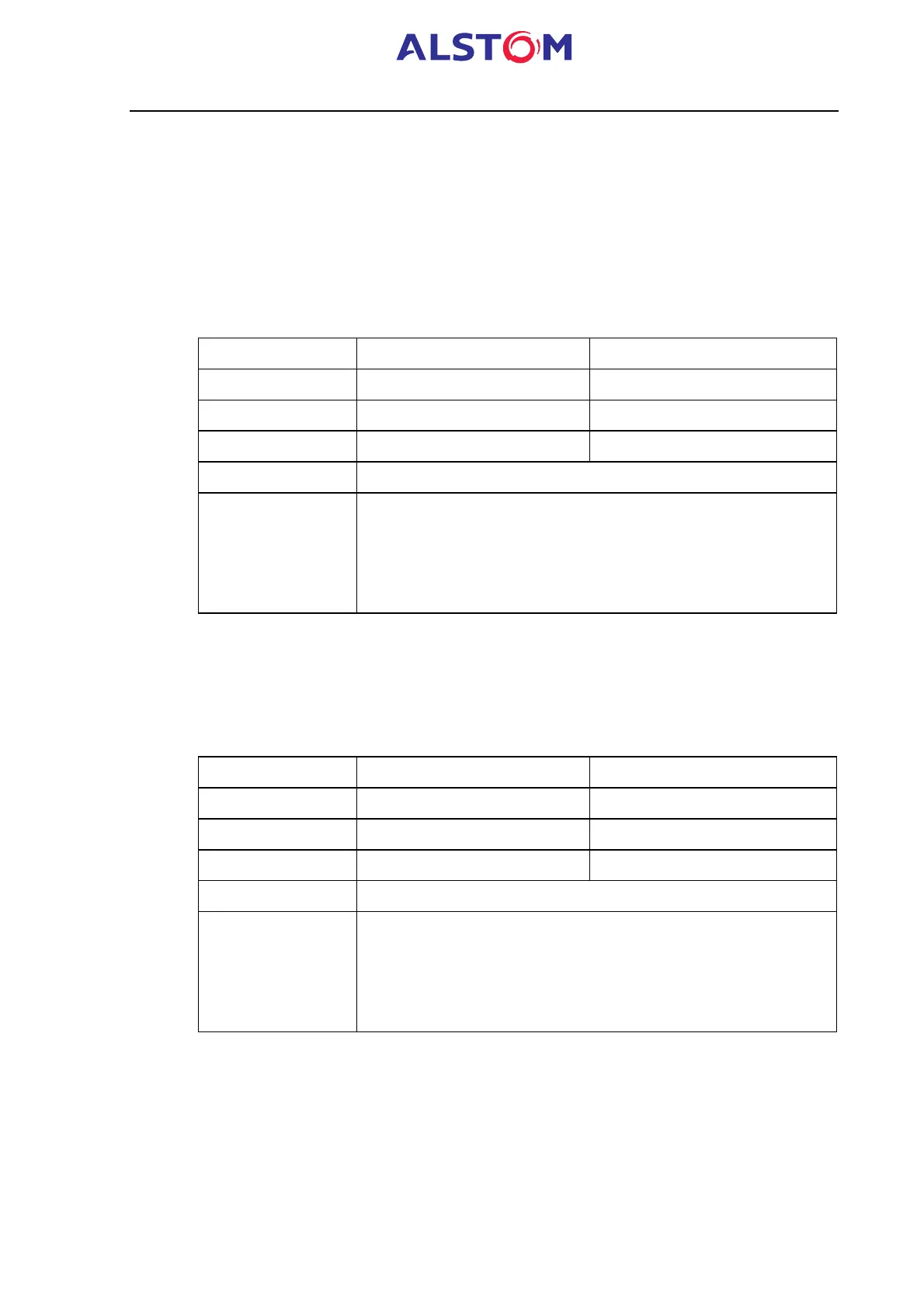
4.2 Disturbance record (P922 and P923)
The MiCOM P922-P923 is able to store up to 5 records of 2.5s each.
Setting Range Step Size
Pre – time 0.01 – 2.5s 0.01s
Post – time 0.01 – 2.5s 0.01s
Sample rate 32 samples/cycle Fixed
Digital signals Logic inputs and output contacts status
Trigger logic - Power on of the MiCOM relay,
- Any selected protection alarm or trip,
- Dedicated logic input,
- Remote command.
NOTE : if both post- and pre-time are set equal to 2.5s, the pre-time will
be priority and equal to 2.5s. The post-time will then be equal to
0s.
4.3 Frequency disturbance record (P923 only)
The MiCOM P923 is able to store one record of 20s.
Setting Range Step Size
Pre – time 5s fixed
Post – time 15s fixed
Sample rate 1 sample/cycle fixed
Digital signals Logic inputs and output contacts status
Trigger logic - Instantaneous or time delayed tripping,
- Dedicated logic input,
- Logic equation,
- Remote command.