Technical Guide P92x/EN FT/E11
User Guide
MiCOM P921-P922-P923 Page 11/110
4. MENU COLUMNS OF THE MiCOM P922 RELAY
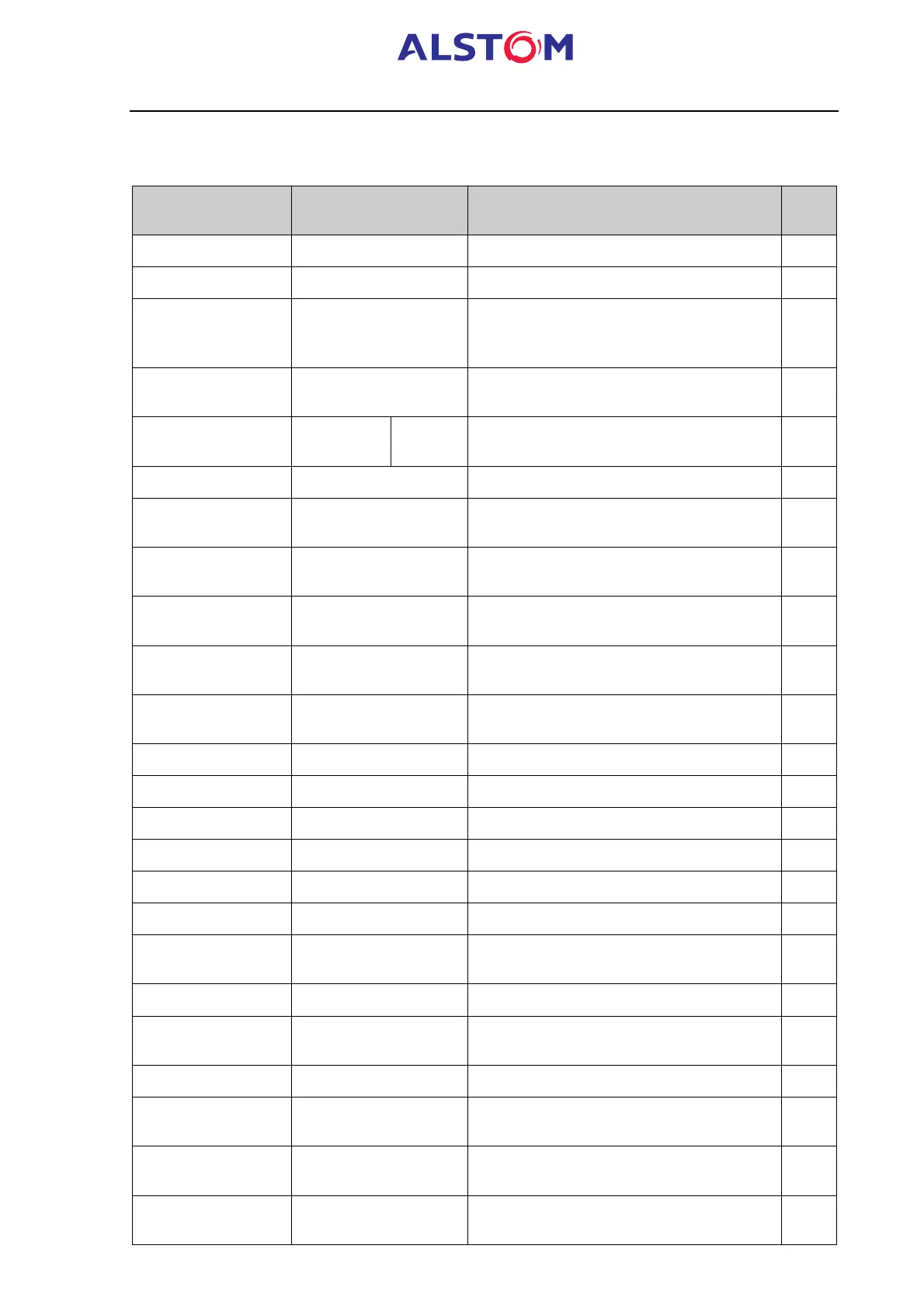
The menu of the MiCOM P922 is divided into columns which are:
HEADINGS OF
COLUMN
SUB – MENUS DESCRIPTION See at
PAGE
OP PARAMETERS General settings and data for the relay 16
CONFIGURATION 18
GENERAL Configuration of the default display, of the
connection and of the protection (phase-
phase or phase-neutral)
19
VT RATIO Settings of the primary and secondary
rated voltages of VTs
20
LED LED 5 to
LED 8
Configuration of the programmable LEDs 21
CONFIG SELECT Selection of the active settings group 26
ALARMS Configuration of the instantaneous self
reset, alarm battery.
27
CONFIGURATION
INPUTS
Logic input configuration, selection of
voltage type applied to the logic inputs
28
MEASUREMENTS Directly measured and calculated
quantities
30
COMMUNICATION Information on the rear active protocol and
choice of the associated settings
35
PROTECTION G1 Configuration of the protective features –
Group 1
39
[27]UNDERVOLTAGE Undervoltage settings 40
[59]OVERVOLTAGE Overvoltages settings 41
[59N]RESIDUAL O/V Residual O/V settings 44
[47]NEG SEQ O/V Negative sequence overvoltage settings 46
[27D]POS SEQ O/V Positive sequence undervoltage settings 47
[81]FREQUENCY Under/over frequency settings 48
PROTECTION G2 Configuration of the protective features –
Group 2 (identical to Group 1)
39
AUTOMAT. CTRL 55
TRIP OUTPUT RLY Allocation of the selected information to
the trip output contact (RLI)
55
LATCH OUTPUTS Selection of the latched information 58
BLOCKING LOG1 t Allocation of the selected information to
the blocking logic function 1
62
BLOCKING LOG2 t Allocation of the selected information to
the blocking logic function 2
64
AUX OUTPUT RLY Allocation of the selected information to
the auxiliary output contacts (RL2 to RL8)
65