The above dimensions are for reference only, the actual product shall prevail"
〖Fixing Installation Panel〗
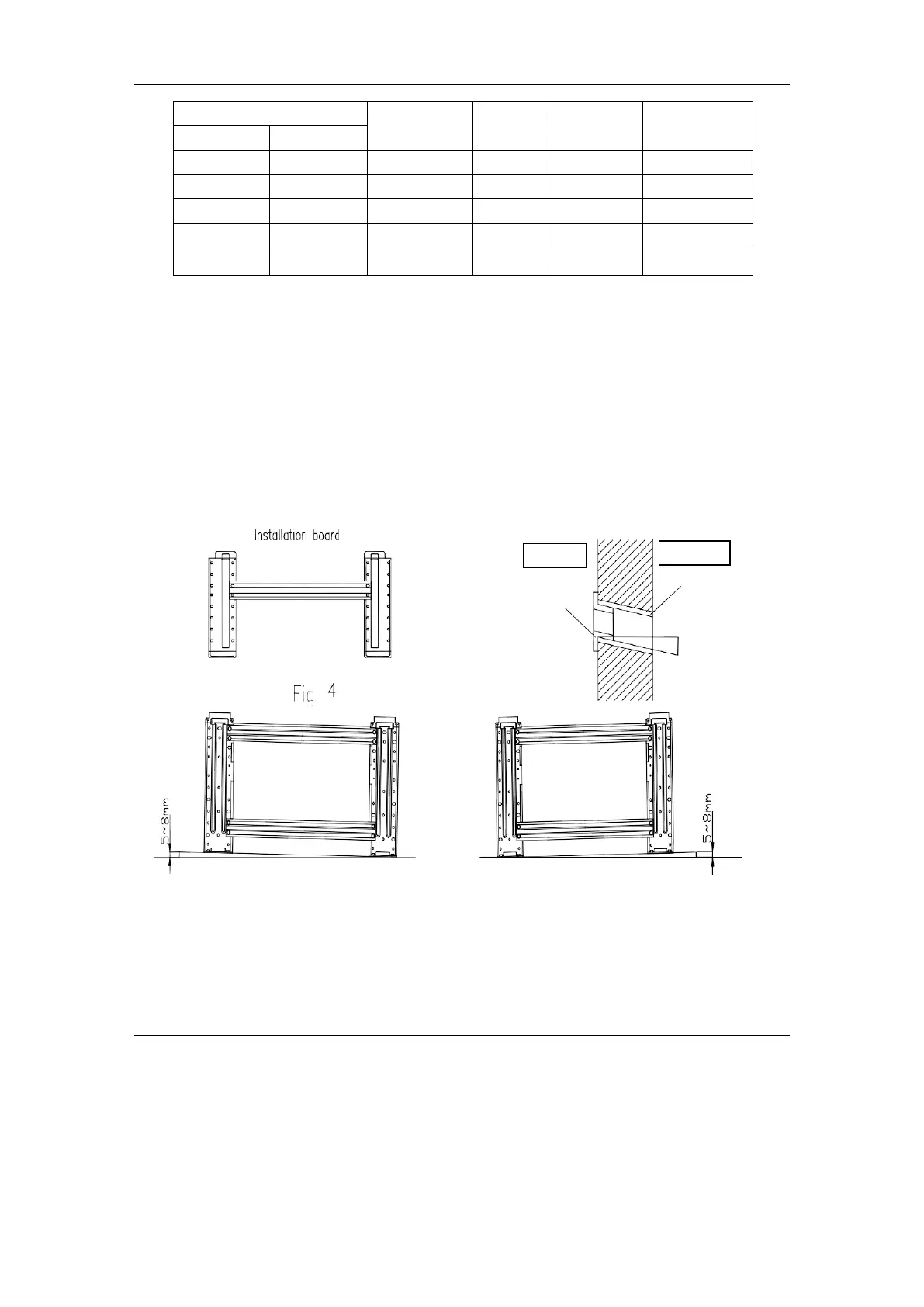
⚫ Dismantle the metal installation board of the indoor unit. Adjust the mounting panel to horizontal
position.
⚫ Drill holes and insert plastic expansion tubes at the appropriate locations on the wall and fix the
installation board on the wall with M5x30 screws and washer 6. Ensure that there must be at least 4
fixed points in the wall. Ensure installation board to horizontal position.
⚫ Drill holes as Fig. 4 shows. The hole, 80mm in diameter, should slightly slide down outwards..
⚫ Cut PVC tubes at a slight angle in the length shorter than wall thickness and inset it into the
hole.( Fig.5)
⚫ Mount the wall cap.
Left side
Right side
Wall cap
Wall
PVC tube
Small angle
Fig.5