〖Connection of Wires〗
1. Indoor unit
⚫ Open upward the inlet grid to the greatest extends.
⚫ Remove the electric cover from the unit.
⚫ Loose the screw at connection lid. (Fig.12)
⚫ Dismantle the wire pressure plate.
⚫ Connect the power connecting wires and signal control
wire separately to the corresponding terminals. (In Fig.14,
please choose the same wiring diagram just with the wiring diagram of unit .)
⚫ Loose off the screw on the earth plate; press earth wire tightly.
⚫ Press tightly the connecting wires of the unit with lead wire pressure plate.
⚫ Close the connection lid screw it tightly and close the inlet grid.
2. Outdoor unit
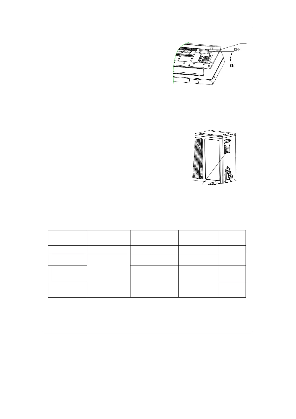
⚫ Unscrew and dismantle the electronic device lid(Fig.13).
⚫ Dismantle the pressure plate of wire fastener.
⚫ Connect the connecting wires of the unit separately to the
corresponding terminals. (Fig.14)
⚫ Press tightly the connecting wires of the unit with top pressure
plate.
⚫ Remount the electronic device lid to the original position.
If user wants to prolong or replace the power wire, please do it according to
the table(Table3).
Electric cover
Fig.13
Table 3