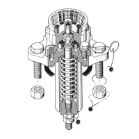
Disassembly of the spring and stem
1. Clean the stem threads with a wire brush and lubricate the threads with a light oil, like WD-40.
2. Loosen and remove the locknut, item #11. Do NOT remove the spring adjustment nut at
this time.
3. Measure and record the distance from the end of the stem to the spring adjustment nut.
This dimension will be used at reassembly.
4. Place the valve into a press with the spring in the upward position and a means to prevent the stem
from dropping out.
5. Using a press yoke to allow access to the spring adjustment nut, compress the valve spring to
remove all force from the nut. Remove the adjustment nut.
6. Slowly back off the press head until the valve spring, item #14, expands to the relaxed state.
7. Remove the spring follower, item #13, the spring guide, item #15, and the spring, item #14.
8. Remove the valve body and stem from the press taking care to prevent the stem from
dropping out.
9. Lay the valve body on its side and withdraw the stem.
Inspection of Valve Components
Top Stem Guide
The inside of the top stem guide should be free of paint, debris, nicks, burrs or other discontinuities.
Visually inspect the inside of the guide and the mating area on the upper stem. Any sign of significant
wear should be reported to ARI Engineering for review and disposition.
Valve Stem
Remove all scale, residue and other foreign material from the stem with a wire brush. Inspect the stem
for signs of corrosion or pitting. Any evidence of corrosion or pitting is grounds for replacement.
The seating surface and O-ring contact areas can be cleaned with 400 grit emery cloth. Any discontinuity
that would prevent sealing is grounds for replacement. Machining, grinding, welding or other alterations
are not permitted.
The stem must be inspected for cracking using either magnetic particle or dye penetration inspection
methods. Cracking is unacceptable. If found, the stem must be replaced.
Place the stem in a set of V-blocks and measure straightness with a dial indicator. The stem must be
straight within .015 TIR. If out of tolerance, the stem must be replaced. Straightening by bending or heat
is not permitted.
O-Ring Retainer
Clean the O-ring setting surfaces inside the retainer with 400 grit emery cloth. Visually inspect the
O-ring grooves. They must be free of pits, corrosion or gouges that would prevent proper sealing of
the O-rings.
American Railcar Industries, Inc.