FOR MODELS: JGI, JGM, JGN, JGP AND JGQ SECTION 5 - MAINTENANCE
PAGE 5-16 9/08
cap.
4. After installing new bearings, check jack and thrust clearances against the clear-
ance limits. If clearances are out of limits, contact your packager or Ariel. Record
values on a copy of the form on Page 5-48.
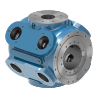
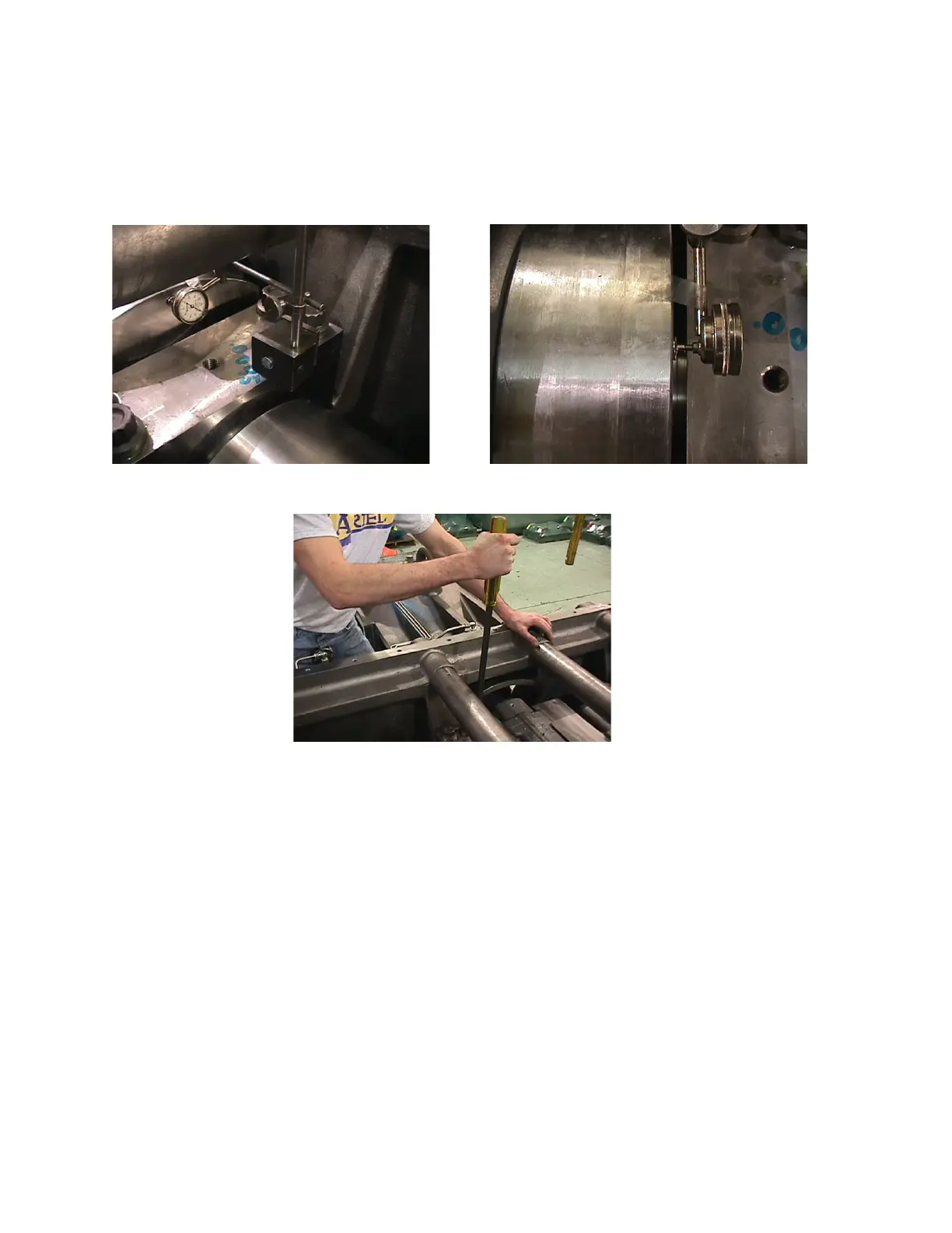
FIGURE 5-11 MEASURING CRANKSHAFT THRUST CLEARANCE
Dial Indicator Magnetic Stand Placement
on Top of Main Bearing Cap
Button Type Dial Indicator Placement
against the side of Crankshaft Web
Use a Pry Bar against Compressor Frame, Thrusting Crankshaft Back & Forth
 Loading...