G
georgebrownJul 30, 2025
What to do if my Ariens 915055 will not crank?
- DDeborah BennettJul 30, 2025
If your Ariens Lawn Mower will not crank, charge or replace the battery.
What to do if my Ariens 915055 will not crank?
If your Ariens Lawn Mower will not crank, charge or replace the battery.
Purpose and intended audience of the service manual.
Information on ordering parts and service inquiries.
Activating warranty registration for the unit.
Warning against using non-Ariens parts and potential warranty voiding.
Ariens reserves the right to make product changes without notice.
Types of communications from Ariens Technical Service.
Explanation of safety symbols and their meanings.
Defines general reference and important information notations.
Safety precautions related to equipment use and limitations.
Comprehensive safety guidelines for operating the unit.
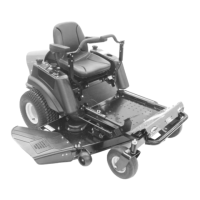
Identification and description of unit controls and features.
Instructions for moving the unit without the engine running.
Safe procedures for refueling the unit.
Lubrication points and intervals for unit maintenance.
Procedure for engaging and disengaging front axle locks.
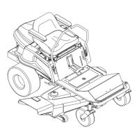
Step-by-step guide for detaching the mower deck.
How to level the mower deck and adjust its cutting pitch.
Setting anti-scalp rollers to prevent lawn scalping.
Procedure to adjust the transmission for proper neutral setting.
Adjusting steering levers for straight-line unit travel.
Procedure for adjusting the parking brake linkage.
Common engine problems, causes, and corrective actions.
Daily procedure for checking the engine oil level.
Steps for draining and refilling engine oil.
Ensuring proper engine cooling through air intake checks.
Routine cleaning of the air cleaner element and cover.
Procedure for replacing a clogged air cleaner element.
Inspection of muffler and spark arrester for damage or corrosion.
Information on spark plug type, gap, and replacement.
Detailed steps for removing the engine from the unit.
Procedure for installing a new or rebuilt engine.
Instructions for removing and installing the PTO belt.
Guide for removing and installing mower blades.
Procedure for sharpening and balancing mower blades.
Common problems, causes, and corrective actions for the hydro transmission.
Recommended fluids for Hydro-Gear transaxles.
Steps for removing the Hydro-Gear transmission assembly.
Procedure for replacing the hydrostatic drive belt.
Description of the manual mower deck lift system.
Steps for removing the mower deck lift system components.
Operation and adjustment of steering controls.
Adjusting steering lever height based on serial number.
Troubleshooting common fuel system problems.
Description of the impulse style fuel pump.
Identifying and addressing fuel contamination issues.
Information on the composite fuel tank material.
Procedure for safely removing the fuel tanks.
Specialized tools and test equipment for electrical diagnostics.
Using meters to measure voltage, current, and resistance.
Procedures for battery care, removal, installation, and charging.
How to test normally open and normally closed switches.
Understanding and testing solenoids and relays.
Diagnosing issues in the unit's lighting circuits.
Purpose of fuses and methods for checking them.
Explanation of diode function and testing rectifiers.
How the electric clutch engages and disengages attachments.
Specific electrical system details for units above serial number 10,000.
Component layout of the electrical system for specific models.
Schematic diagrams for the electrical system of units above 10,000.
Visualizing continuity states for electrical components above 10,000.
Specific electrical system details for units between serial numbers 5,000 and 9,999.
Component layout for electrical systems of units 5,000-9,999.
Schematics for electrical systems of units 5,000-9,999.
Visualizing continuity states for electrical components 5,000-9,999.
Specific electrical system details for units below serial number 5,000.
Component layout for electrical systems of units below 5,000.
Schematics for electrical systems of units below 5,000.
Visualizing continuity states for electrical components below 5,000.
Procedure for removing mower spindle assemblies.
| Engine | Briggs & Stratton |
|---|---|
| Cutting Width | 21 inches |
| Drive Type | Self-Propelled |
| Weight | 85 lbs |
| Cutting Height Positions | 6 |
| Deck Material | Steel |
| Mulching Capability | Yes |
| Bagging Capability | Yes |
| Side Discharge Capability | Yes |
| Product Type | Lawn Mower |
| Wheel Size | 8 in (front) / 11 in (rear) |
| Warranty | 3 years limited |