EN - 10
ASSEMBLY
Tools Required
• Pliers
• Open-End Wrenches: 3/8, 7/16, 1/2,
9/16" and/or Adjustable Wrench
•Tire Gauge
• Torque Wrench (Optional)
• Phillips Screwdriver
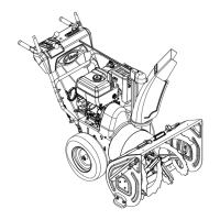
Unfold Lower Handlebar
(Figure 4)
IMPORTANT: Be sure to block wheels or
secure unit so it does not move during
assembly.
1. Rotate lower handlebar out from unit
so
lower
handlebar mounting holes align
with mounting holes on the unit frame
(Figure 4).
.
2. Secure lower handlebar to unit using two
3/8" x 3/4" hex head serrated fl
ange
gr
ade 5 bolts (Figure 3, It
em 2)
3.
Tighten all four bolts to 25 – 42 lbf-ft
(33.9 – 56.9 N•m).
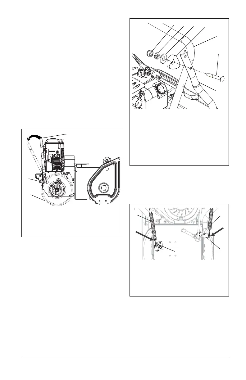
Attach Upper Handlebar Assembly
(Figures 5 and 6)
1. Attach upper handlebar assembly to
lower handlebar using two sets of the
handlebar hardware. One set to attach
each side of the handlebars (Figure 5).
NOTICE: DO NOT tighten hardware. Allow
upper handlebar assembly to hang from the
lower handlebars for the next step (Figure 5).
.
2. Hook spring end of attachment control
cable t
o the clutch arm.
3. Hook spring end of the traction cont
rol
cable t
o the cable eyelet on back of
frame.
.
Unfold Upper Handlebar Assembly
(Figures 7 and 8)
1. Rotate the handlebar into operat
ing
posit
ion.
NOTICE: Be careful not to damage cable
spring hooks when rotating handlebar
upward.
Figure 4
1
2
1. Lower Handlebar
2. Wheel
3. Mounting Hole
3
Figure 5
3
4
2
1. Upper Handlebar Assembly
2. Lower Handlebar
3. 5/16" x 2-1/4" Round Head S
quare
Nec
k Grade 5 Bolt
4. Handlebar Spacer
5. Flat Steel Washer
6. Locking Washer
7. 5/16" Nyloc Nut
1
7
6
5
Figure 6
3
1. Clutch Arm
2. Cable Eyelet
3. Attachment Control Cable
4. Traction Control Cable
1
4
2
 Loading...