EN - 11
.
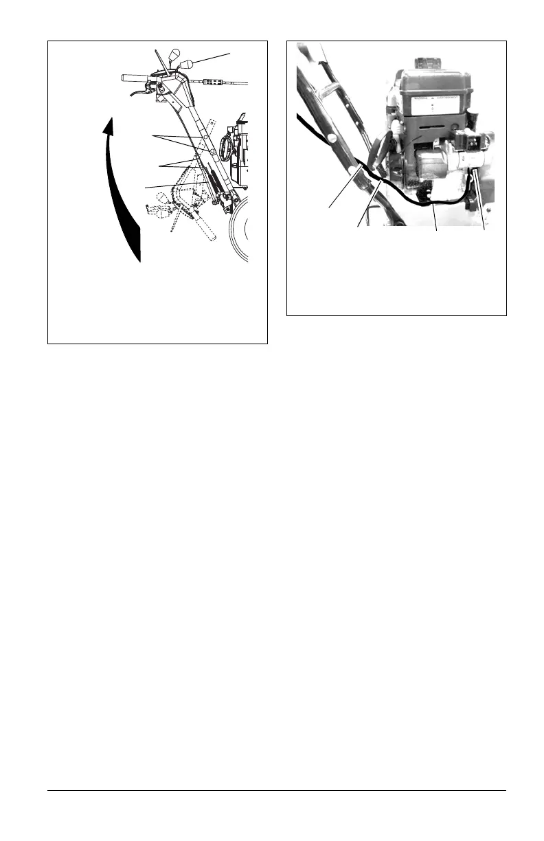
2. Install the remaining handlebar
hardware attaching t
he upper handlebar
as
sembly to the lower handlebar
(Figure 5).
3. Tighten all hardware.
4. Remove packaging around shift rod.
5. Rotate shift rod into place and tight
en
ha
rdware.
6. Connect shift rod to speed select
or arm
an
d adjust as specified in S
peed
S
elector Adjustment on page 31.
7. Adjust attachment cable as specif
ied in
A
ttachment Clutch/Brake Adjustment
on
page
32.
8. Adjust the traction cable as specif
ied in
T
raction Drive Clutch Adjustment
on
page
34.
Connect Headlight Wire Harness
(Figure 8)
NOTICE: The headlight wire harness comes
attached to the upper handlebar assembly.
1. Route the wire harness along the interior
of the right side handlebar.
2. Connect to the engine electrical plug.
3. Press cable anchor into mounting hole in
the frame near the engine electrical
plug.
4. Secure the wire harness to t
he
handlebars
using the cable ties attached
to the wire harness.
Install Trigger Cable Assembly
(Model 921023)
(Figure 9)
NOTICE: Trigger cable assembly comes
attached to the Sno-thro unit.
1. Attach remote trigger cable assembly to
upper handlebar assembly using on
e
1/
4" x 1-1/2 oval head machine scr
ew
(F
igure 3, Item 14) and one 1/4" lo
cking
w
asher (Figure 3, Item 15) (Figure 9).
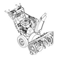
Figure 7
1. Handlebar Hardware
2. Shift Rod Hardware
3. Shift Rod
4. Speed Selector Lever
1
3
2
4
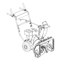
Figure 8
2
4
3
1. Wire Harness
2. Cable Tie
3. Cable Anchor
4. Engine Electrical Plug
1

 Loading...