REPAIR MANUAL
Page: 4
A 45 V
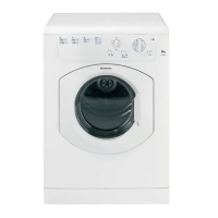
5. CONTROL PANEL COMPONENTS
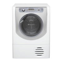
• To remove the On / Off Switch and Start Switch (Fig. 5-1) or the LED Indicators (Fig. 5-2) first remove the Control Panel as
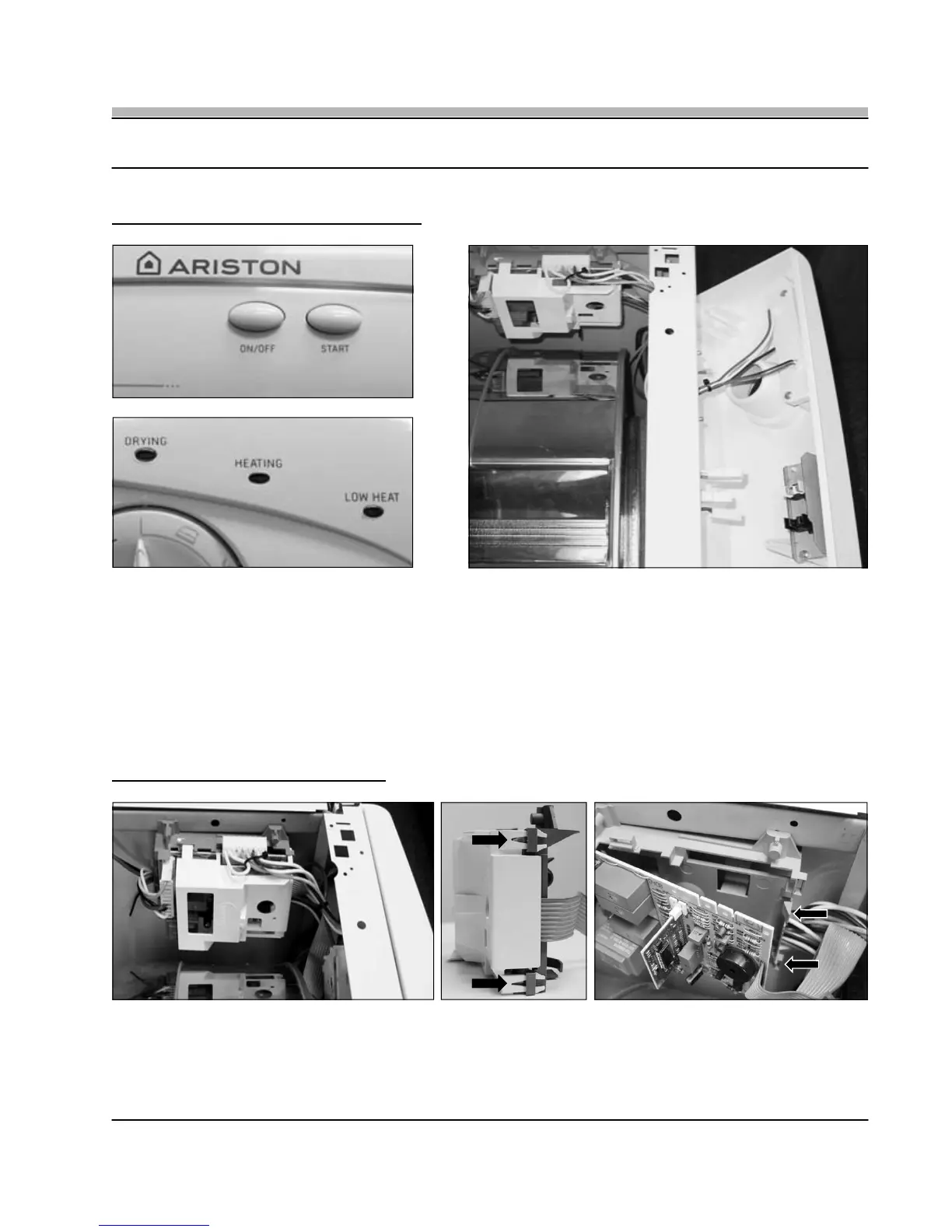
described in Section 4. With the Control Panel Mounting Screws removed, angle the Control Panel down to allow access to the
LED Assembly (A) or the Microswitch Assembly (B) (Fig. 5-3). Either component can be replaced by removing the two (2) Phillips
screws that secure the assemblies in place.
TECH NOTE: The On / Off and Start Buttons can be replaced without removing the Control Panel. First mask the area to protect
against damaging the Control Panel, then carefully insert a small screwdriver between the bottom of the Button and
the Control Panel and then carefully pry the Button out and off.
Fig. 5-2
A
B
Fig. 5-3
Fig. 5-1
6. DRYNESS SENSOR MODULE
Fig. 6-1
Fig. 6-2
Fig. 6-3
• To remove the Dryness Sensor Module, first remove the Module Cover (A) (Fig. 6-1) by unlatching the two (2) Module Cover
Latches located on the front top and bottom of the Module Housing (Fig. 6-2). Then swing the Module Cover out and off removing it
from its rear hinge. With the Module Cover removed disconnect the wiring and then slide the Module Board out from the Module
Housing by pressing the two (2) Sensor Board Release Latches (Fig. 6-3).
A