16
installazione installation
Collegamento Periferiche
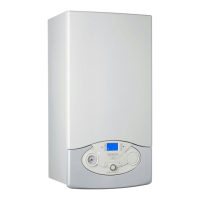
Per accedere alle connessioni delle periferiche procedere come segue:
- scollegare elettricamente la caldaia
- rimuovere il carter sganciandolo dal portastrumenti
- rimuovere il mantello frontale
- sganciare le due clip “a”, ruotare in alto il pannello “b” per accedere
al collegamento delle periferiche
- svitare le due viti “c” e rimuovere il coperchio “d” del portastrumenti
per accedere alla scheda elettronica.
Peripheral unit connection
To access peripheral unit connections carry out the following steps:
- Disconnect the boiler from the power supply
- Remove the casing by unhooking it from the instrument panel
- Rotate the control panel while pulling it forwards
- Unhook the two clips “a”, rotate the cover “b” to have access to the
peripherical connections
- Unscrew the two screws “c” and remove the cover “d” of the
instrument panel to have access to the main P.C.B.
a
b
c
d
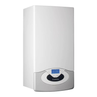
Connessioni periferiche:
BUS = Collegamento periferiche modulanti
TA2 = Termostato ambiente Zona 2
SE = Sonda Esterna
TNK = Sonda Bollitore (CLAS EVO SYSTEM)
SOL = Sonda solare
TA1 = Termostato ambiente Zona1
Peripheral connections:
BUS = Remote control connection
TA2 = Room thermostat 2
SE = Outdoor sensor
TNK = Tank sensor (CLAS EVO SYSTEM)
SOL = Solar temperature probe
TA1 = Room thermostat 1
Collegamento termostato ambiente
- allentare il fermacavo con un cacciavite e inserire il cavo
proveniente dal termostato ambiente
- collegare i cavi al morsetto TA1, rimuovendo il ponticello
- assicurarsi che siano ben collegati e che non vengano messi in
trazione quando si chiude o si apre lo sportello portastrumenti
- richiudere lo sportellino, richiudere lo sportello portastrumenti e
il mantello frontale.
Attenzione!
Per il collegamento ed il posizionamento dei cavi delle
periferiche optionali vedere le avvertenze relative
all’installazione delle periferiche stesse.
Room thermostat connection
- Introduce the thermostat wire
- Loosen the cable clamp using a screwdriver and insert the wires
leading from the room thermostat one at a time.
- Connect the wires to the terminals TA1, removing the jumper
- Make sure that they are well connected and that they are not subject
to traction when the control panel lid is opened or closed
- Close the ap again, then replace the control panel cover and the
front casing.
Caution!
For the connection and positioning of the wires belong-
ing to optional peripheral units, please refer to the
advice relating to the installation of these units.
BUS
T
B
TA2 SE
TNK
SOL
TA1
BUS
T B
TA2
SETNK SOLTA1
CN1
Controllo Remoto
Remote Control
Sonda Esterna
External Sensor
Termostato Ambiente1
Room Thermostat 1
Sonda Bollitore (*)
Tank Sensor (*)
(*) = CLAS EVO SYSTEM
OK
Sensys
1234567
 Loading...