24
installation
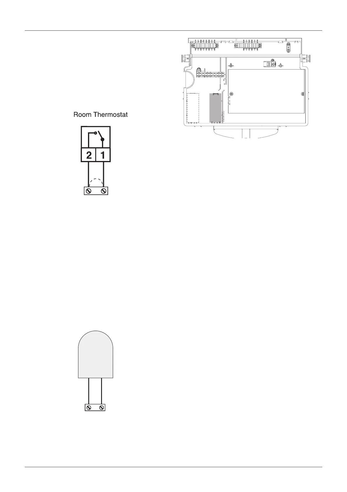
Room thermostat connection
- Introduce the thermostat wire
- Loosen the cable clamp using a screwdriver and insert the
wires leading from the room thermostat one at a time.
- Connect the wires to the terminals as indicated in the gure
below, removing the link
- Make sure that they are well connected and that they are
not subject to stress when the control panel lid is opened or
closed
- Close the ap again, then replace the control panel cover and
the front casing.
Outdoor sensor connection
- Introduce the outdoor sensor wires
- Loosen the cable clamp using a screwdriver and insert the
wires leading from the outdoor sensor one at a time.
- Connect the wires to the terminals as indicated in the gure
below;
- Make sure that they are well connected and that they are
not subject to stress when the control panel lid is opened or
closed;
- Close the ap again, then replace the control panel cover and
the front casing.
- Refer to page 39 for setting the parameters when using the
outdoor sensor.
Note: wheN coNNectiNg the boiler to exterNal coNtrols, do
Not ruN 240V cables aNd cables for switchiNg circuits
(which are low Voltage) together, use seperate cables to
preVeNt iNduced Voltage oN the low Voltage circuits.
Connector TA on PCB
(low voltage switching)
CARTE CHAUDIERE
AMPC-GAL1
Transmetteur BUS
(Optionnel)
Emplacement
carte optionnelle
SETA1
Connector SE on PCB
Outdoor Sensor

 Loading...