Do you have a question about the Ariston CLAS X and is the answer not in the manual?
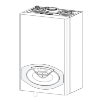
Technical dimensions and physical layout of the boiler models.
Exploded view of internal components for sealed chamber FF models.
Exploded view of internal components for sealed chamber FF SYSTEM models.
Exploded view of internal components for open chamber CF models.
Diagrams illustrating the internal hydraulic circuits for Combi and System models.
Description and layout of the boiler's user interface and control buttons.
Explanation of icons and symbols shown on the boiler's display screen.
Step-by-step process of the boiler's operation during heating mode.
Step-by-step process of the boiler's operation during domestic hot water mode.
Function for boiler combustion analysis and gas calibration.
Reduces hot water output time by keeping primary circuit warm.
Protects the boiler from freezing by activating pump and burner.
Checks for proper water flow and flow rates to prevent errors.
Function to remove residual air from the primary circuit.
Adjusts heating restart delay based on setpoint temperature.
Diagram and identification of components in the Combi hydraulic unit.
Diagram and identification of components in the System hydraulic unit.
Operation, positions, and anti-sticking function of the 3-way valve.
Details on the stepper motor for the 3-way valve, including disassembly.
Description of the secondary exchanger and antiscale limit temperatures.
Temperatures for limiting scale formation in the secondary exchanger.
Information on pump types and operational control.
Methods to check pump speed using parameter or voltage measurement.
Details on pump and valve behavior after switching off different modes.
Minimum pressure switch settings and safety shutdown.
Procedure for filling the heating circuit using the tap.
Procedure for emptying the heating system using the drain valve.
Automatic by-pass function for protecting the heat exchanger.
Description and dimensions of the primary heat exchanger.
Location and procedure for inspecting and cleaning the heating return filter.
Function, features, and pressure charts for the expansion vessel.
Operation of the DHW flow meter and filter.
Use of NTC1 and NTC2 sensors for temperature readings and error codes.
Description of the SIT 845 SIGMA gas valve and its functions.
Procedures for gas pressure and power regulation.
Procedure for checking the gas supply pressure for different gas types.
Procedure for checking and adjusting maximum sanitary power output.
Procedure for checking and adjusting minimum power output.
Procedure for checking and adjusting soft ignition power.
Table of gas pressures and heat input values for CF models.
Table of gas pressures and heat input values for FF models.
Regulation of the delay time between heating request and burner ignition.
Setting the maximum heating power for heating and sanitary modes.
Comprehensive table of gas parameters, consumption, and settings.
Description of the burner, electrodes, and nozzle diameters.
Sequence of operations for ignition in sanitary and heating modes.
Description of the fume discharge collectors for coaxial and twin-pipe systems.
Function of the differential pressure switch for fume evacuation.
Details on the types of fans used in the boilers.
Post-ventilation times for various switching off conditions and faults.
Control system for smoke exhaust using an automatic reset thermostat.
Specifications for smoke exhaust systems for sealed chamber FF models.
Specifications for smoke exhaust systems for CF open chamber models.
Description of the main electronic control card (GALEVO2 SE).
Wiring diagram for FF models showing connections to components.
Wiring diagram for CF models showing connections to components.
How to connect external devices like room thermostats and sensors.
Accessing and navigating the technician menu for parameter adjustment.
Overview of the complete menu structure for boiler settings.
Parameters related to user interface settings like display and backlight.
General boiler parameters such as DHW setpoint.
Settings for controlling heating zone 1, including setpoint and thermoregulation.
Settings for controlling heating zone 2, including setpoint and thermoregulation.
Settings for controlling heating zone 3, including setpoint and thermoregulation.
Settings for the zone module, including manual mode and hydraulic schemes.
Service parameters for boiler statistics, burner, and temperature readings.
Overview of error types: shutdown, safety stop, and indication.
Detailed list of error codes, their descriptions, and reset methods.
