22
installation
The maximum permissible ue length for twin ue is
dependent on the type of run used (see table below).
For further information relating to ue runs not illustrated,
please contact the Technical Department on 0870 241 8180.
For coaxial systems, the maximum ue lengths listed in the
table below take into account an elbow.
For twin ue systems the maximum ue lengths listed in the
table below includes the exhaust gas/air intake terminal.
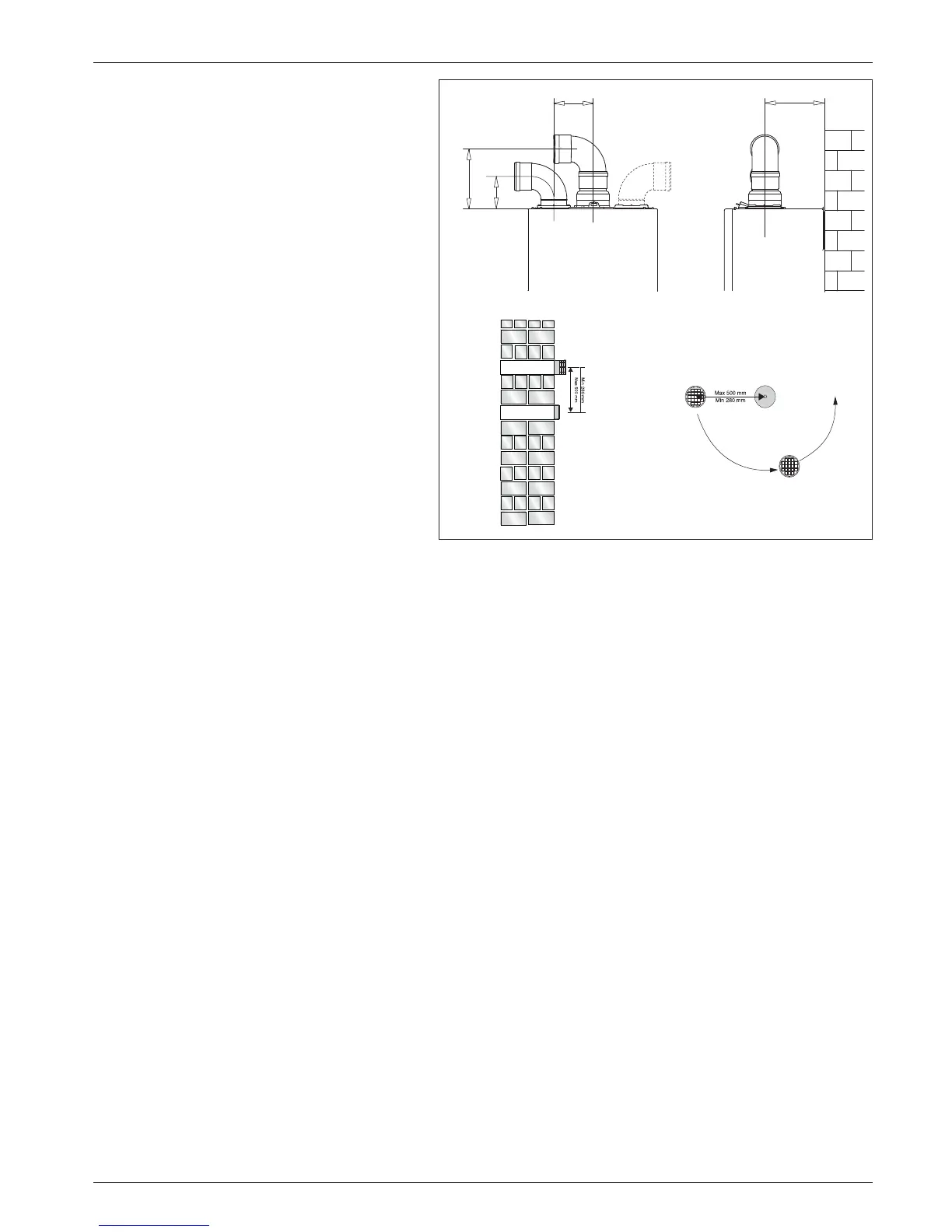
Type 5 outlets should respect the following instructions:
1- Use the same ø 80 mm ue pipes for the air intakes and
exhaust gas ducts.
2- If you need to insert elbows in the air intake and exhaust
gas ducts, you should consider for each one the equivalent
length to be included in the calculation of developed
length.
3- The exhaust gas duct should jut above the roof by at least
0.5 m.
4- The intake and exhaust gas ducts in Type C13 and C53
must be installed on the same wall, or where the exhaust
is vertical and the air intake horizontal, the terminals must
be on the same side of the building.
EXHAUST
AIR INTAKE
AIR INTAKE
AIR INTAKE MUST NOT BE
FITTED ABOVE THE EXHAUST
195
105
120
180
Fig. 9
Fig. 10

 Loading...