40 /
SETTINGS - ADJUSTMENT - PROBLEM IDENTIFICATION MENUS
menu
sub-menu
Parameter
Description value
default setting
27 1 Bleed cycle press OK button for 5 seconds see First Ignition parag.
2 8 RESET MENU’ 2
280Automatically resetting to the default setting
in menu 2
Reset
OK = yes
ESC = no
To reset all default parameter
settings, press the OK button
4 ZONE 1 PARAMETER
4 0 ZONE 1 TEMPERATURE SETTING
402Heating fi xed temperature setting
“Heating fi xed temp”
from 35 to 82 °C
(high temperature - para. 420
=1)
70 Activated only with temperature
control and fi xed temperature
(see 421)
from 20 to 45 °C
(high temperature - para. 420
=0)
20
4 2 ZONE 1 SETTING
420Heating appliance temperature value setting 0 = from 20 to 45°C
(low temperature)
1 = from 35 to 85°C
(high temperature)
select in the appliance type
base
421 Basic heating control type selection type
depending on the peripheral devices
connected
0 = fi xed fl ow temperature
1 = device On/Off
2 = room sensor
3 = external sensor only
4 = room sensor +
external sensor
1 To activate heating control,
press the AUTO button. The
display lights up the AUTO
symbol
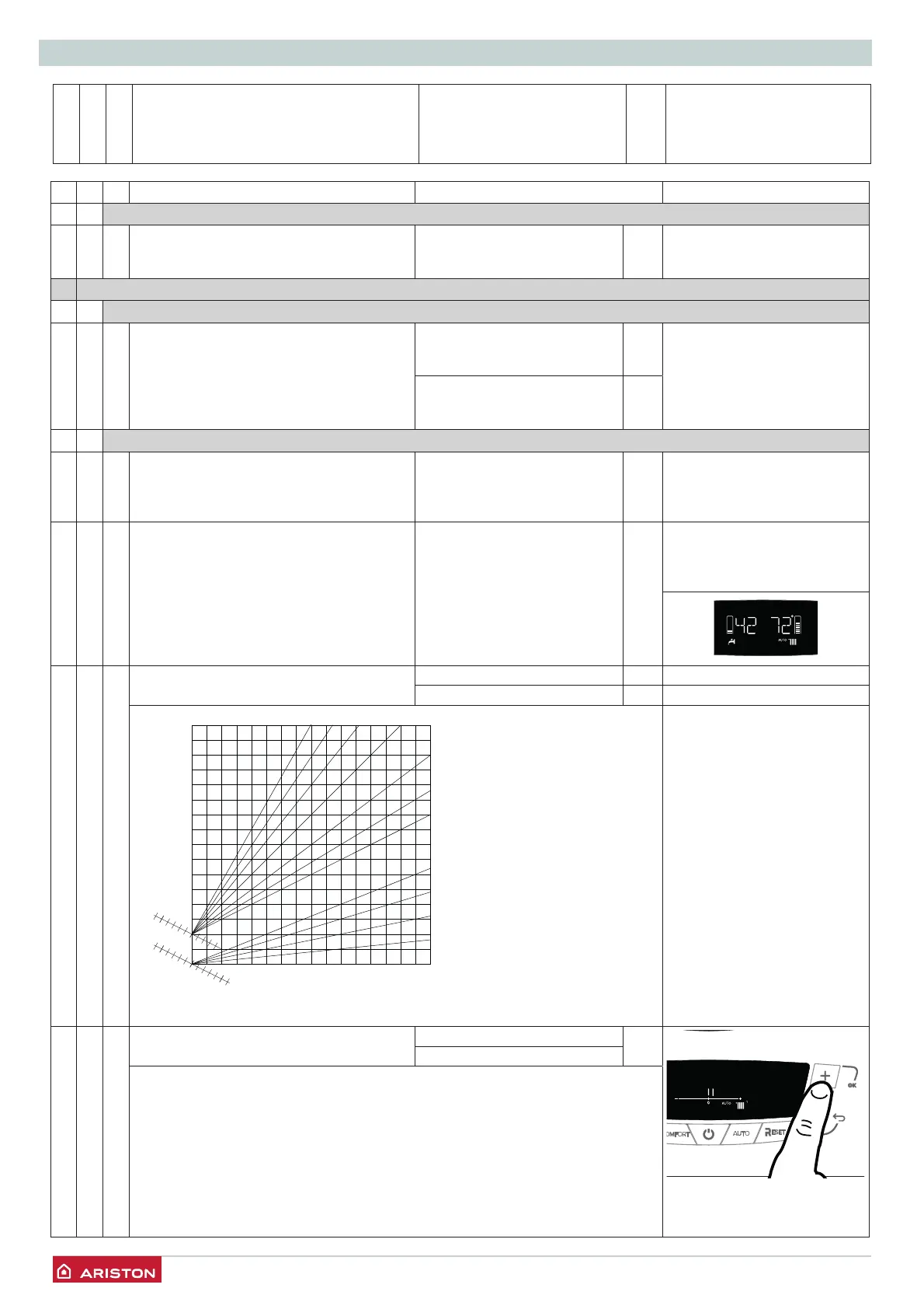
422Slope from 0_2 to 0_8 (low temperature)
from 1_0 to 3_5 1_5 (high temperature)
Flow Temperature
Low temperature High temperature
External temperature
Ambiente temperature
setting value
°C
20
25
15
30
40
50
60
70
80
90
100 °C
10
2.5 3.0 3.5 2.0
1.5
1.2
1.0
0.8
0.6
0.4
0.2
5 0 -5 -10 -15 -20 °C
If the external sensor is used,
the boiler calculates the
most suitable heating fl ow
temperature taking the external
temperature and the type of
appliance into account.
The type of curve must be
chosen according to the type of
appliance radiator and the heat
losses present in the building.
423 Parallel shift from - 7 to + 7 (low temperature) 0
from - 14 to + 14
(high temperature)
To adapt the thermal curve to the appliance requirements, it is possible to perform
a parallel shift of the curve in order to alter the calculated fl ow temperature and
therefore the ambient temperature.
By accessing this parameter or pressing the buttons 8 the curve can be shifted in a
parallel manner as indicated in the fi gure shown below.
The value is indicated on the display:
- from -7 to +7
(low temperature)
- from -14 to +14
(high temperature)
Each step represents a fl ow temperature increase/decrease of 1°C in relation to the
set-point value.




 To Next Page