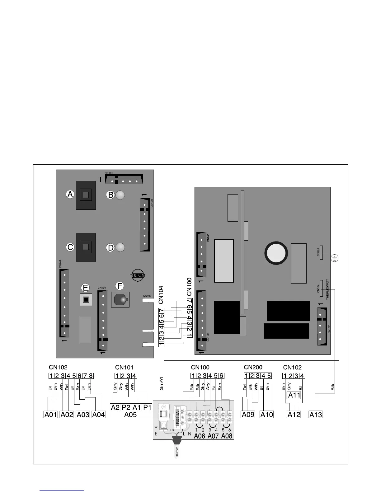
EasyManuals Logo
Home>Ariston>Boiler>microSYSTEM 21 RFFI

Ariston microSYSTEM 21 RFFI Installation Instructions

Ariston microSYSTEM 21 RFFI
48 pages
To Next Page IconTo Next Page
To Previous Page IconTo Previous Page
Page #43 background imageLoading...
Page #43 background image
19
B063
3. ELECTRICAL
DIAGRAMS
SE011A
L
EGEND:
A - On/Off Switch
B - On/Off L.E.D.
C - Heating Switch
D - Heating L.E.D.
E - Reset Button
F - Ignition Failure (Lockout) L.E.D.
A01 - Pump Pressure Switch
A02 - Frost Thermostat
A03 - Modulator
A04 - Circulation Pump
A05 - Regulation Thermostat
A06 - External Control System
A07 - Time Clock Connector
A08 - External (Room) Thermostat
A09 - Air Pressure Switch
A10 - Fan
A11 - Overheat Thermostat
A12 - Spark Generator/Gas Valve Supply
A13 - Detection Electrode
Colours:
Wh -White
Bl -Blue
Gry -Grey
Brn -Brown
Blk -Black
Rd -Red
Grn/Yll-Yellow/Green

Table of Contents

Other manuals for Ariston microSYSTEM 21 RFFI

Questions and Answers:

Question and Answer IconNeed help?

Do you have a question about the Ariston microSYSTEM 21 RFFI and is the answer not in the manual?

Ariston microSYSTEM 21 RFFI Specifications

General IconGeneral
BrandAriston
ModelmicroSYSTEM 21 RFFI
CategoryBoiler
LanguageEnglish

Related product manuals