2000 SERIES SENSORS INSTALLATION GUIDE Revision 3.1 June 1997
There are 4 different Mounting Bases available for the 2000 Series Sensors:
DB2001 : sensor base without remote LED connectors (Ø 10 cm)
DB2001U : sensor base without remote LED connectors (Ø 15 cm)
DB2002 : sensor base with remote LED connectors (Ø 10 cm)
DB2002U : sensor base with remote LED connectors (Ø 15 cm)
When sensors with remote LED drivers are being installed (for example DT2073,
DI2072, DP2071), the DB2002 or DB2002U should be used.
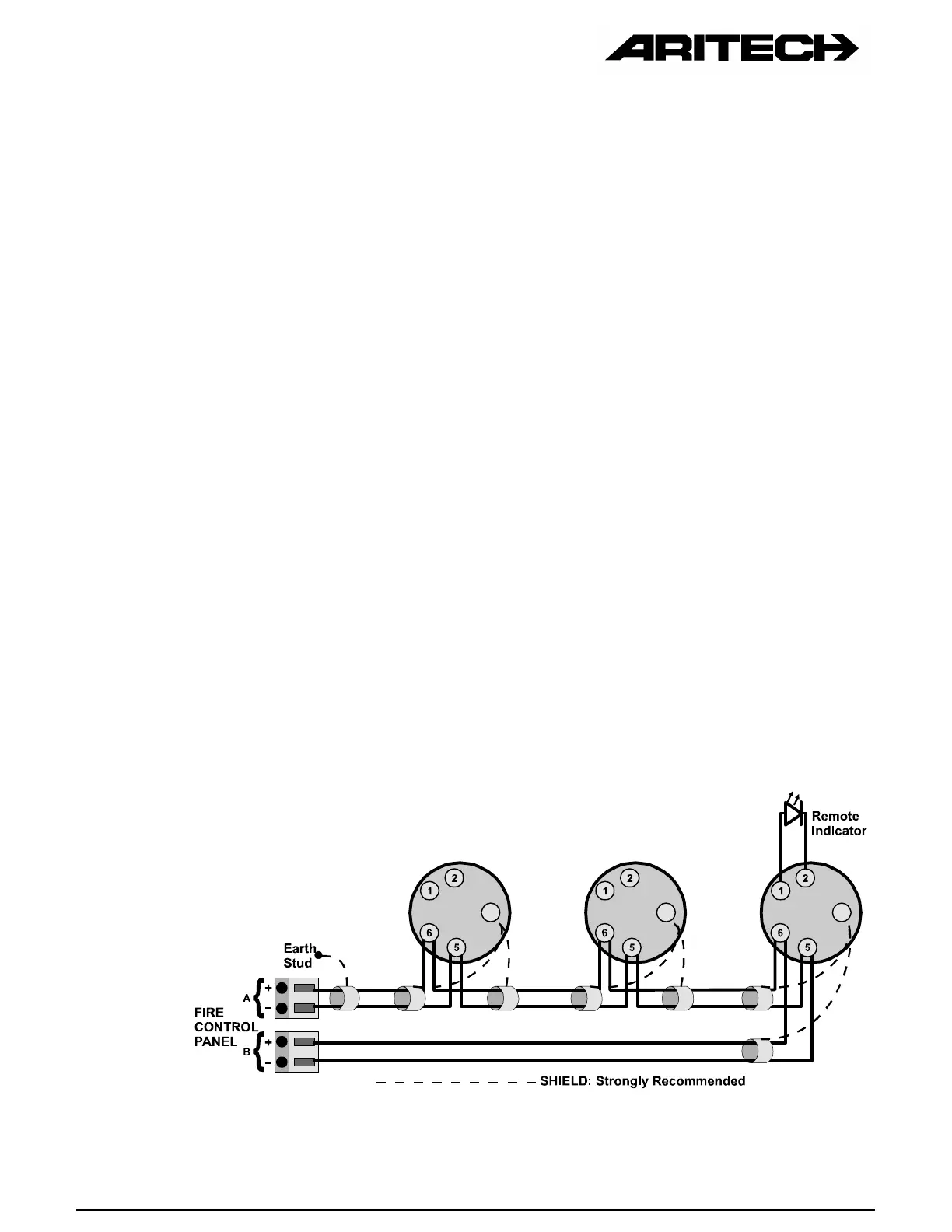
Please refer to Figure 1 for Class A, and Figure 2 for Class B (no return) wiring.
It is not necessary to observe polarity on terminals 5 and 6 as the fire monitors are not
polarity sensitive, but when the remote LED driver is being used, polarity must be
observed !
To install a detector head, insert the head and rotate it clockwise until it is properly
aligned and "sets" into the base (Figure 3). Then rotate it an additional 15º to lock it in
place.
Each 2000 Series Universal Mounting Base is equipped with a moulded locking
mechanism to prevent unauthorised removal of the sensor head (Figure 4). If you want
detectors to be locked into the base, remove tab before inserting into the base. To
remove the sensor head, insert a small screwdriver into the slot on the side of the base
and press in while simultaneously turning the sensor head counter clockwise (Figure 5).
The different Aritech Mounting Bases are designed so that the fire sensors will not
operate in the Isolator Mounting Base DB2003 and vice versa. The 2000 Series Range
of Fire Sensors will also not fit the base of another Aritech Range of Sensors.
A ground shield is strongly recommended, but not required. The shield must be
connected to the earth ground at one point only, preferably via an earth stud in the fire
control panel.
Address tags are available to write the address of the detector on. The address tag
should be positioned before the base is mounted.
Figure 1 : Class A Wiring
 Loading...