EasyManua.ls Logo

Aritech DDI602AM - User Manual

Aritech DDI602AM
48 pages
Print Icon
To Next Page IconTo Next Page
Loading...
© 2020 Carrier 1 / 48 P/N 146655999-1 (ML) • REV G • ISS 14DEC20
DDI602AM Outdoor Dual PIR/AM Detector
Installation Sheet
EN
DE
ES
FR
IT
NL
PL
PT
SE
2
3
4
5
6

Table of Contents

Question and Answer IconNeed help?

Do you have a question about the Aritech DDI602AM and is the answer not in the manual?

Overview

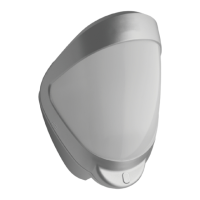
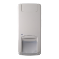
The DDI602AM Outdoor Dual PIR/AM Detector is an external motion detector and alarm trigger that utilizes two independent passive infrared (PIR) detectors and a microwave sensor module. It is designed for outdoor installations and offers programmable options, including a variable pulse count and a choice of three detection ranges: 10 m, 20 m, and 30 m.

Technical Specifications:

  • Detection Range: Programmable for 10 m, 20 m, or 30 m.
  • Coverage: 10 to 70° detection angle, with a maximum coverage of 30 x 24 m.
  • Adjustment: Pan adjustment from -45° to +45°, tilt adjustment up to +45°.
  • Fresnel Lens: Features 28 zones for each detection element, which can be masked with curtain sliders.
  • Customized Optics: Double silicon shielded quad element optics eliminate 50,000 lux of white light.
  • LEDs:
    • Top PCB: Red (Programming LED).
    • Sensor PCB: Blue (Detector alarm), Red (small, Anti-Mask alarm), Infrared (Walk tester communication), Red (PIR active), Green (Microwave active).
  • Radar Frequency Band: 8.5 to 10.6 GHz.
  • Operating Frequencies (country specific):
    • DDI602AM-F1: 10.525 GHz
    • DDI602AM-F2: 10.587 GHz
    • DDI602AM-F3: 9.900 GHz
  • Maximum Power Output (E.I.R.P.):
    • DDI602AM-F1: 27 dBm
    • DDI602AM-F2: 27 dBm
    • DDI602AM-F3: 14 dBm
  • Outputs:
    • NO (Normally Open): Volt-free relay, signal contact 24 VAC/DC at 50 mA with an integral 25 Ω series resistor. Alarm time: 5 seconds.
    • NC (Normally Closed): Volt-free relay, signal contact 24 VAC/DC at 50 mA with an integral 25 Ω series resistor. Alarm time: 5 seconds.
    • Fault/Mask: Volt-free relay, signal contact 24 VAC/DC at 50 mA with an integral 25 Ω series resistor.
  • Power Input: 10 to 15 VDC.
  • Current: 21 mA (12 V nominal), Standby 41 mA MAX.
  • Pulse Count: 1 or 2.
  • Temperature Compensation: Analog (thermistor) and digital sensitivity adjustment.
  • Control: Digital microprocessor with nonvolatile memory.
  • Walk Test: Output test mode with LED indication. Option to disable LEDs.
  • Operating Temperature: -30 to +65°C.
  • Housing: High impact ABS plastic with HDPE cover, UV stabilized.
  • Dimensions (W x H x D): 125 x 175 x 130 mm.
  • Weight: 365 g net, 551 g gross.
  • Mounting Height: Variable up to 6 m, optimum 3 m for full range.
  • Environmental Class: IP55.

Usage Features:

  • Mounting: The detector should be mounted considering that the PIR sensor is more sensitive to movement across beams, while the microwave sensor is more sensitive to movement towards and away from the sensor. A minimum 10 cm (4 inches) clearance above the detector housing is recommended. For side-by-side mounting, a minimum 1 m (3.3 ft) separation is required, but no minimum space is needed for back-to-back mounting. The recommended optimum mounting height is 3 m. The unit comes with a drilling template for easy installation.
  • Cable Entry: A razor knife is used to open a rubber seal for cable entry. Standard eight-core or 12-core alarm cable should be fed through the wall and into the cable entry. It is recommended to seal cable entries and screw mounting holes from within the detector using acrylic (non-silicone based) sealants to prevent moisture ingress.
  • Tamper Protection: The unit must be screwed tightly to the wall to ensure the tamper pin is correctly located and the tamper micro-switch is closed. Two spare tamper feet (1 mm shorter and 1 mm longer than the original) are provided for uneven surfaces.
  • Multibeam Alignment and Masking: The multifunction lens produces seven long-range and seven medium-to-short-range curtain PIR beams. The detector module has two sliding shutters to reduce the detection angle. Additional curtain sliders are provided for further narrowing of the beam pattern. Self-adhesive silver mask can be applied to the lens to mask off specific beams (vertically or horizontally) to avoid unwanted detection. The lens is marked "TOP" for correct orientation.
  • Programmable Options:
    • Pulse Count: Configurable to 1 or 2. A pulse count of 1 makes the detector most sensitive, requiring one detection before signaling an alarm.
    • Detection LED: Can be enabled (ON) or disabled (OFF). When ON, the blue detection LED signals detection.
    • A-M Output: Can be programmed to activate both "Alarm and Fault" relays or only the "Fault" relay. For Grade 3 compliance, "Alarm and Fault" must be selected.
  • Programming Mode: Settings are adjusted using a programming button and indicated by the red programming LED. The detector stores all settings in nonvolatile memory.
  • Walk Test Mode: Activates the blue detection LED to indicate presence. It is initiated by pressing the programming button once and automatically ends five minutes after the last detection. The front cover must be in place during walk tests to ensure correct beam pattern and range.
  • TEOL/DEOL Configuration: Jumpers allow configuration of internal Triple End-of-Line (TEOL) or Double End-of-Line (DEOL) resistor values for Alarm, Tamper, and Fault/Anti-Mask outputs. Discrete resistors can also be connected directly to the outputs.

Maintenance Features:

  • Fault/Anti-Mask Circuit: This technology prevents deliberate disabling of the detector by monitoring for obstruction. The Fault/Anti-Mask relay may remain open for the first two minutes after installation or walk test initiation.
  • Self-Calibration: The detector performs an automatic self-calibration after 2 minutes in walk test mode, requiring the front cover to be securely fitted. Self-calibration also occurs every evening during decreasing ambient light and every morning during increasing light to compensate for dirt buildup on the front cover and prevent false Fault/Anti-Mask detections.
  • Voltage Check: The unit self-tests the supply voltage. If the voltage is out of specification, the Fault/Anti-Mask relay will open until the supply voltage is within specification.
  • Remote Self-Test: A self-test routine starts when a negative voltage is applied to the TEST terminal. The Anti-Mask detector continuously self-checks and activates the Fault/A-M relay if an internal fault condition is detected.
  • Remote LED Operation: LEDs are enabled when a negative voltage is applied to the LED terminal.
  • Resetting Options: The detector can be reset to default settings by removing power, holding the programming button, and reapplying power. This can be done before installation with a PP3 battery or on-site with 12 V power.

Accessories:

  • Carrier Fire & Security offers a handheld walk tester (DI601-WT) to assist with installations.

Aritech DDI602AM Specifications

General IconGeneral
BrandAritech
ModelDDI602AM
CategorySecurity Sensors
LanguageEnglish

Related product manuals