P/N 146251999-4-ML • REV M • ISS 10JUN21 3 / 38
EN: Installation Sheet
Introduction
The EV1116 series includes the EV1116 and EV1116AM PIR
motion sensors. They have a patented mirror, pyro and signal
processing technology.
WARNING! The equipment is not earthed. Any
external circuit connected to the equipment must be
located within the same building and connected to a
protective earthing conductor.
Wire insulation of cables connected to the equipment must
conform to IEC 60332-1-2 and IEC 60332-1-3 or IEC 60332-
2-2, depending on the wire cross sectional area, or IEC TS
60695-11-21, regardless of cross sectional area. Alternatively,
such wires must comply with UL 2556 VW-1.
Installation guidelines
The technology used in these detectors resists false alarm
hazards. However, avoid potential causes of instability (see
Figure 1) such as:
• Direct sunlight on the detector
• Strong draughts onto the detector
• Heat sources within the detector field of view
• Animals within the detector field of view
• Obscuring the detector field of view with large objects,
such as furniture
• Objects within 50 cm (20 in.) of the anti-masking (AM)
detector
• Installing two detectors facing each other and less than
50 cm (20 in.) apart (only AM detectors)
Installing the detector
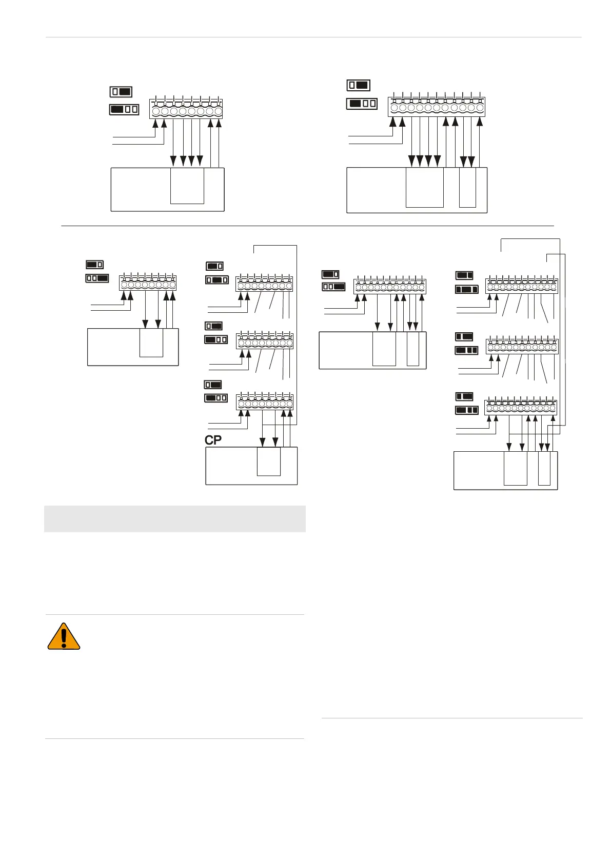
Figure 7
(1): Standard connection (factory
default)
(2): Dual loop connection
CP: Control panel
WT: Walk test
AM: Antimasking
D/N: Day/night
Rtest: Remote test
EV1116
EV1116AM
EV1116 EV1116AM
Zone X
1
2
3
4
5
6
7
GND
+12V
Alarm
Alarm
Tamper
WT
Tamper
J3
J4
8
D/N
CP
Zone Y
+12V
Tamper
WT
Tamper
1
2
3
4
5
6
7
8
9
10
GND
Alarm
D/N
AM
AM
Alarm
Zone X
J3
J4
11
Rtest
CP
Zone Y
+12V
Tamper
WT
Tamper
1
2
3
4
5
6
7
8
9
10
GND
Alarm
D/N
AM
AM
Alarm
Zone X
J3
J4
Zone Y
+12V
Tamper
WT
Tamper
GND
Alarm
D/N
AM
AM
Alarm
Zone X
+12V
Tamper
WT
Tamper
GND
Alarm
D/N
AM
AM
Alarm
J3
J4
J3
J4
J3
J4
11
Rtest
1
2
3
4
5
6
7
8
9
10
11
1
2
3
4
5
6
7
8
9
10
11
1
2
3
4
5
6
7
8
9
10
11
Rtest
Rtest
CP
CP
Zone X
1
2
3
4
5
6
7
GND
+12V
Alarm
Alarm
Tamper
WT
Tamper
J3
J4
Zone X
GND
+12V
Alarm
Alarm
Tamper
WT
Tamper
GND
+12V
Alarm
Alarm
Tamper
WT
Tamper
GND
+12V
Alarm
Alarm
Tamper
WT
Tamper
J3
J3
J4
J3
J4
8
D/N
1
2
3
4
5
6
7
8
1
2
3
4
5
6
7
8
1
2
3
4
5
6
7
8
D/N
D/N
D/N
J4
CP
(1)
()2
Normal
larmA
Tamper
Short
AM/TF
4.7 k
9.4
0
Ω
kΩ
Ω
88
Normal
larmA
Tamper
Short
AM/TF
4.7 k
9.4
0
Ω
kΩ
Ω
88
Normal
larmA
Tamper
Short
4.7 k
9.4
0
Ω
kΩ
Ω
8
Normal
larmA
Tamper
Short
4.7 k
9.4
0
Ω
kΩ
Ω
8
+12V
Tamper
WT
Tamper
GND
Alarm
D/N
AM
AM
Alarm
Rtest
Normal
larmA
< 33 Ω
8
Normal
larmA
< 33 Ω
8

 Loading...