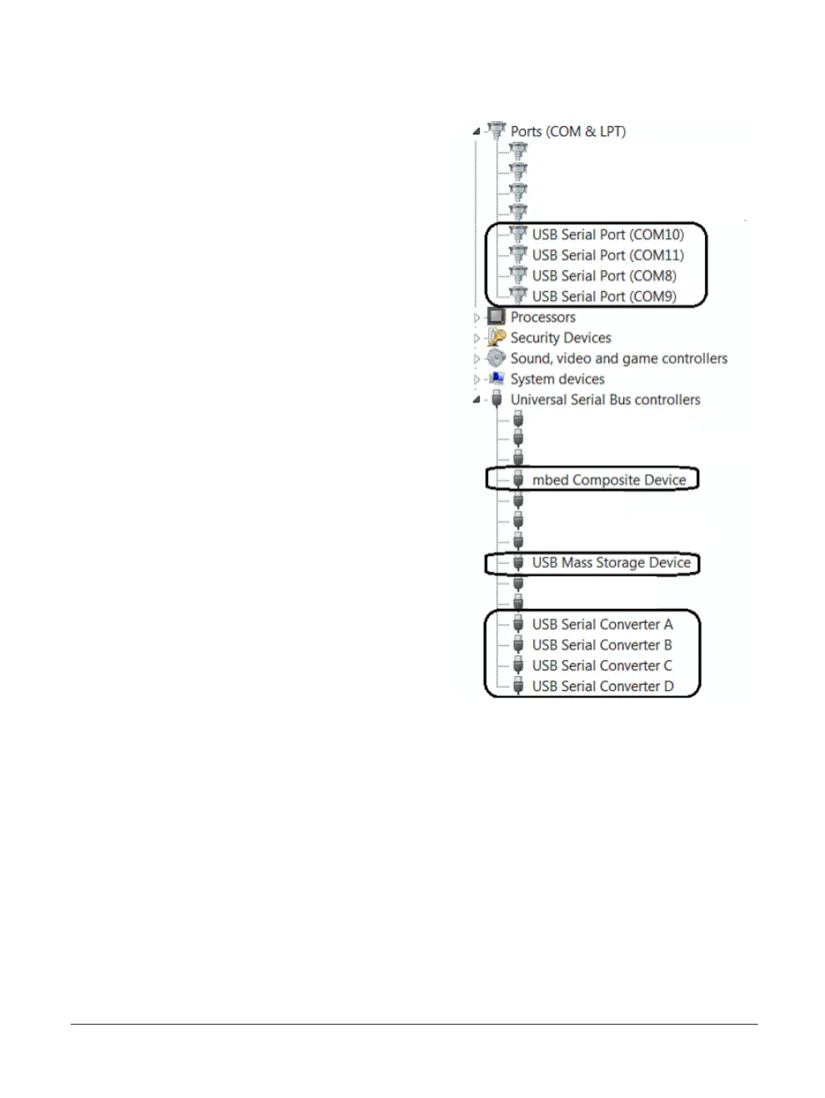
The following figure shows the USB devices that the MPS3 board adds when you connect a workstation
to the USB debug connector.
Figure 2-26 MPS3 board software drivers
Related information
A.1.1 20-pin IDC connector on page Appx-A-71
A.1.2 10-pin IDC connector on page Appx-A-72
A.1.3 20-pin Cortex debug and ETM connector on page Appx-A-72
A.1.4 38-pin MICTOR connector on page Appx-A-73
A.1.5 14-pin F-JTAG ILA connector on page Appx-A-74
A.1.6 Debug USB 2.0 connector on page Appx-A-75
1.3 Location of components on the MPS3 board on page 1-15
2 Hardware description
2.18 System debug
100765_0000_04_en Copyright © 2017–2020 Arm Limited or its affiliates. All rights
reserved.
2-52
Non-Confidential