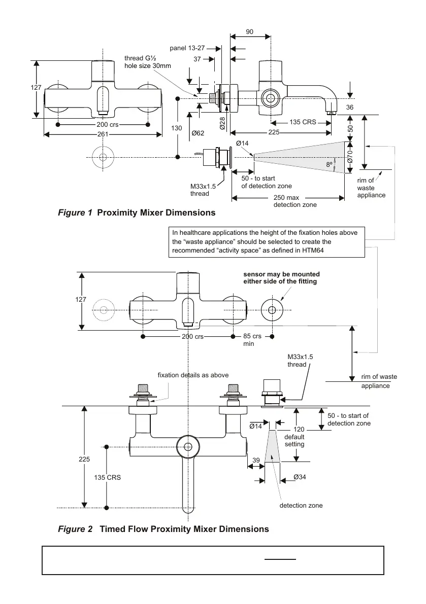
EasyManua.ls Logo

Armitage Shanks Markwik 21 - Page 3

Armitage Shanks Markwik 21
28 pages
Print Icon
To Next Page IconTo Next Page
To Previous Page IconTo Previous Page
Loading...
3
3 DIMENSIONS
Figure 1
Proximity Mixer Dimensions
Figure 2
Timed Flow Proximity Mixer Dimensions
In healthcare applications the height of the fixation holes above
the “waste appliance” should be selected to create the
recommended “activity space” as defined in HTM64
37
panel 13-27
135 CRS
90
36
200 crs
200 crs
261
127
127
Ø62
Ø28
Ø
70
8
º
Ø
14
Ø
14
50 - to start
of detection zone
50 - to start of
detection zone
250 max
detection zone
130
thread
hole size 30mm
85 crs
min
Ø
34
39
120
default
setting
detection zone
50
M33x1.5
thread
M33x1.5
thread
135 CRS
225
fixation details as above
rim of
waste
appliance
rim of waste
appliance
sensor may be mounted
either side of the fitting
IMPORTANT: Prior to installing mixer, ensure that any existing thermostatic mixing
valves (TMVs) that may be tted are removed

Related product manuals