5
5 INSTALLATION: FIXATION
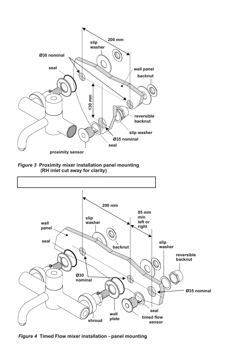
Proximity mixer installation panel mounting
(RH inlet cut away for clarity)
installation - panel mounting
These mixers are designed to be
panel mounted on a duct wall of
maximum panel thickness 27mm.
For thicker panels the rear of the
panel will require counter bores of
62mm or greater around the xa-
tion holes.
Cut two holes of 30mm diameter,
horizontally aligned to 200mm
centres in the wall.(See figure 1
for height positioning of the tting
body over a “waste appliance”)
The sensor will require a hole of
35mm positioned as indicated in
either g1 or g2.
Loosen the chrome shrouds and
insert the tting as shown above
with the wall plates and seals to
the front of the wall.
Put on the slip washers and do up
the backnuts to a torque of 25 Nm
.
Screw the shrouds onto the
wall plates.
Check that all joints are securely tightened, test for leaks.