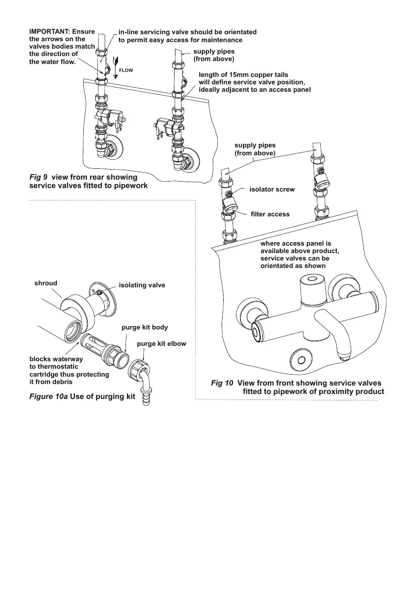
length of 15mm copper tails
will define service valve position,
ideally adjacent to an access panel
Fig 9 view from rear showing
service valves fitted to pipework
Fig 10 View from front showing service valves
fitted to pipework of proximity product
Figure 10a Use of purging kit
in-line servicing valve should be orientated
to permit easy access for maintenance
cartridge thus protecting
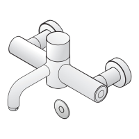
Connect water supply pipes to the ser-
vice valves and make good all the joints.
Check that all connections are water tight.
IMPORTANT NOTE:
Before operating the product, it is strongly rec-
ommended to ush the pipe work to remove
any residues or debris remaining after instal-
lation. A purge kit is available for this purpose.
See below
A purging kit - A4556AA (not included) designed to ush out debris from the pipe-work after installation
is available from Customer Care (see section 18)
Sensor and solenoids must be connected and be operational before purging (see sections 7 & 8)
The following procedure should be used to ush the pipe work:
1.Unscrew and slide back shrouds, close both isolating valves.
2.Remove both maintenance carriers as described in section 13.1.
3.Screw the purge kit bodies into both sides of product. Screw elbows onto the ends of the purge kit
bodies.
4.Open isolating valves then place a hand in the sensor detection zone (to operate the valve).
Allow water to discharge into a receiving vessel.
Note: suitable tubing can be push tted onto elbows if required.
5.Once system has been purged, reverse this procedure.
7
6.1 Flushing with hydro-purging kit