# 45465K005
Page 14
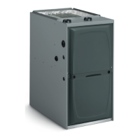
Figure 19
Filter Rack Mounting Hole
Screw
Filter Rack
Corner Embossments
Front of Cabinet
Filter Rack Installation
2. Using the filter rack as a template, mark and drill four
7/64" diameter screw holes in the side panel(s).
3. With the filter access opening toward the front of the
furnace, use sheet metal screws to fasten the rack(s)
to the side panel(s).
4. Install the filter(s) in the rack(s), mesh side of filter
towards furnace.
Model AMB20A external filter is available for single
side return air connection in installations requiring
more than 1600 CFM nominal air delivery.
Horizontal Installations
These furnaces can be horizontally installed for airflow
right to left or left to right. They are to be installed so that
the burner and blower access panels are in a vertical
plane; they are NOT to be installed such that these panels
are in a horizontal plane (see Figure 1 on page 3).
Never install any furnace on its back.
Counterflow (Downflow) Installations
G1D80BR and G2D80CR furnaces may be installed
directly on the supply plenum or coil cabinet if the furnace
is installed on a noncombustible floor.
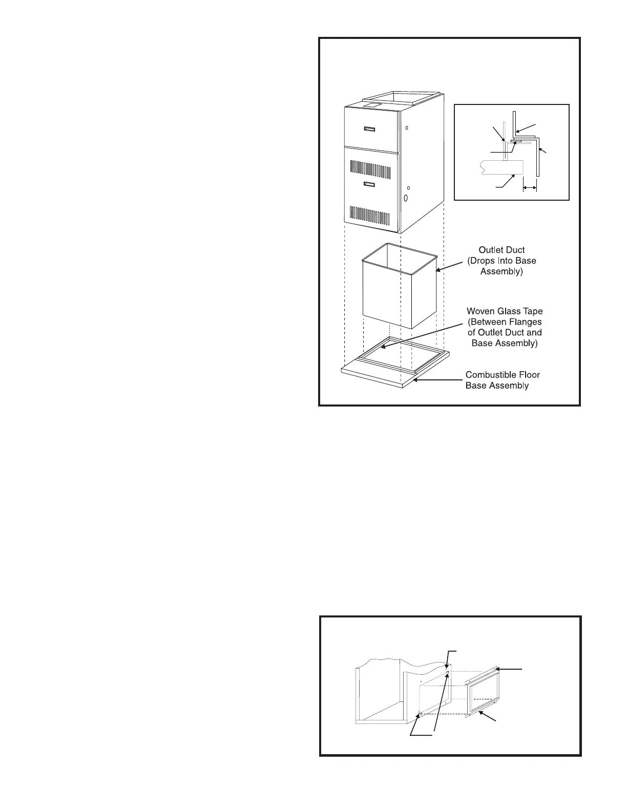
For installations on combustible flooring, a special base
must be ordered and used (refer to the furnace rating
plate for the appropriate base model number). Refer to the
following instructions and Figure 18:
1. Cut a hole in the floor, sized to provide 1" clearance
between all four sides of the duct and the edge of the
flooring. The four angles on the base assembly should
recess into the floor joists and the base should rest on
all four outside flanges.
2. Construct duct connections with 1" to 1-3/4" right
angle flanges, and long enough to extend below the
floor joists.
3. Drop the duct connections through the top of the base
assembly with the right angle flanges in good contact
with the glass tape on top of the base assembly.
4. Carefully position the furnace over the right angle duct
flanges.
Filters
If a filter other than one supplied by the furnace
manufacturer is used, it must be sized according to
information provided in Table 2.
Filters are not supplied with G1D80BR and G2D80CR
series furnaces but their use if required (see Counterflow
Applications on page 15).
Side Return
A filter rack and cleanable 16" x 25" x 1/2" filter are
supplied with each G1D80BT and G2D80CT furnace.
(Models designed for more than 1600 CFM nominal air
delivery include two of each.) The filter rack is to be
installed between the return air duct and the side of the
furnace. Refer to Figure 19 and the following instructions
to install the filter rack:
1. Using the corner embossments as a guide, mark and
cut a full-size opening in the side panel(s).
Figure 18
Combustible Floor Installation
(Counterflow Models Only)
1"
Combustible
Flooring
Woven
Glass Tape
Base
Assembly
Duct
Furnace