# 45465K005 Page 3
These instructions must be placed on or near the
furnace in a conspicuous place.
This furnace is design certified by CSA International as a
Category I furnace using air from inside the structure for
combustion. The combustion system is fan-assisted, which
means it is equipped with an integral mechanical means to
draw products of combustion through the heat exchanger.
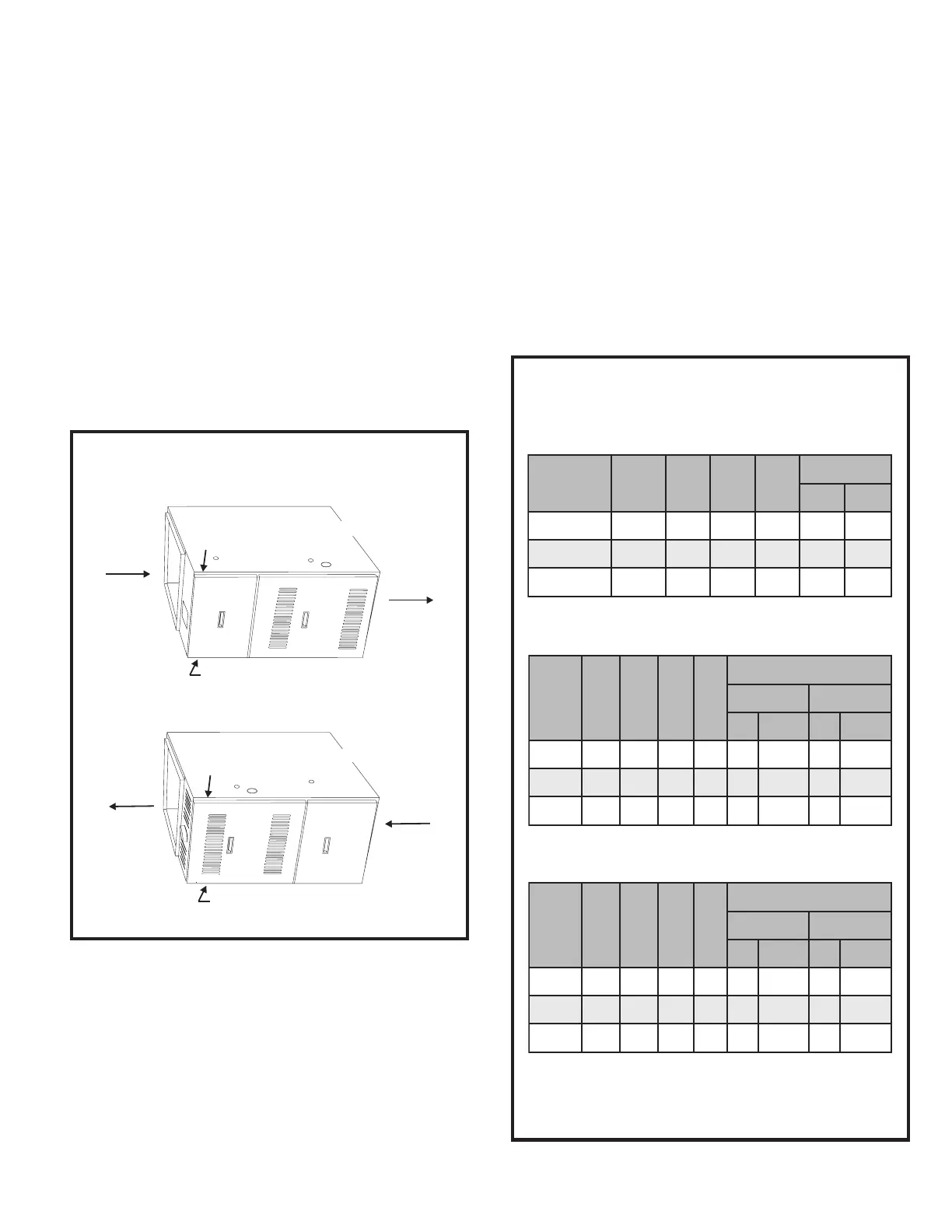
G1D80BT and G2D80CT models may be installed as
upflow furnaces or horizontal furnaces. G1D80BR and
G2D80CR models may be installed as counterflow
(downflow) furnaces or horizontal furnaces. When
installed horizontally, the installer must install a sheet
metal screw to retain the upper door as shown in Figure 1.
Never install any furnace on its back.
Horizontal Installations
Figure 1
INSTALLATION
Locate Screw Here When Horizontal
Installation is Airflow Right to Left
Return
Supply
Locate Screw Here When Horizontal
Installation is Airflow Left to Right
G1D80BR/ ModelsG2D80CR
Return
Supply
Locate Screw Here When Horizontal
Installation is Airflow Left to Right
Locate Screw Here When Horizontal
Installation is Airflow Right to Left
G1D80BT/ ModelsG2D80CT
Inspection of Shipment
This furnace is shipped in one package, completely
assembled and wired. The thermostat is shipped in a
separate carton when ordered.
Upon receipt of equipment, carefully inspect it for possible
shipping damage. If damage is found, it should be noted
on the carrier’s freight bill. Damage claims should be filed
with the carrier immediately. Claims of shortages should
be filed with the seller within 5 days.
Check the rating plate for correct model number, type of
gas, and input.
Clearances
All servicing and cleaning of the furnace can be performed
from the front. If installed in a closet or utility room, provide
18" clearance in front for service if the door to the room is
not in line with the front of the furnace.
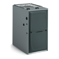
All models are suitable for installation at reduced clear-
ances to combustibles as noted in the tables in Figure 2.
Minimum Clearances to Combustibles
(all measurements in inches)
1
May be 2" when Type B-1 vent pipe is used.
2
May be 1" when Type B-1 vent pipe is used.
3
Where values greater than 0 are shown, may be 0"
when Type B-1 vent pipe is used.
Figure 2
Upflow and Counterflow Installations
Horizontal Installations
(G1D80BR models)
Horizontal Installations
(G2D80CR, G1D80BT, and G2D80CT models)
tenibaC
htdiW
tnorF kcaB poT tneV
sediS
tfeL thgiR
5.714
1
016
2
2
3
0
0.12 4
1
0 1 6
2
0 0
5.424
1
016
2
00
tenibaC
htdiW
ediSs tnorF kcaB tneV
wolfriA
LotR RotL
poT mottoB poT mottoB
5.7108106
2
2
2
012
2
0.12 0 81 0 6
2
1 0 1 0
5.4208106
2
10 10
tenibaC
htdiW
ediSs tnorF kcaB tneV
wolfriA
LotR RotL
poT mottoB poT mottoB
5.7108106
2
13
2
3
2
0
0.12 0 81 0 6
2
1 2
3
2
3
0
5.4208106
2
1000