# 45465K005 Page 17
The furnace must be grounded and wired in accordance
with local codes or, in the absence of local codes, with the
National Electrical Code ANSI/NFPA No. 70 (latest edition)
and/or CSA C22.1 Electrical Code (latest edition) if an
external electrical source is utilized.
In all instances, other than wiring for the thermostat, the
wiring to be done and any replacement of wire shall
conform with the temperature limitation for Type T wire –
63°F (35°C) rise.
Connect a sufficiently sized wire with ground to the furnace’s
line voltage connections and ground lug. Refer to the
furnace rating plate for electrical characteristics to be used
in sizing field supply wiring and overcurrent protection.
The line voltage supply should be routed through a
readily accessible disconnect located within sight of the
furnace. A junction box on the furnace side panel is
provided for line voltage connections. Refer to the furnace
wiring diagram for specific connection information.
Proper polarity of the supply connections (“HOT”
and “NEUTRAL”) must be observed to ensure that
safety controls provide the protection intended.
A connection to the ground lug and actual earth ground
(typically a ground stake or buried steel pipe) must be
maintained for proper operation.
Thermostat
Install a room thermostat according to the instructions
furnished with it. Select a location on an inside wall that is
not subject to drafts, direct sunshine, or other heat sources.
The initial heat anticipator setting should be equal to the total
current draw of the control circuit. Low voltage thermostat
connections are to be made to the integrated ignition/blower
control board as indicated on the wiring diagram.
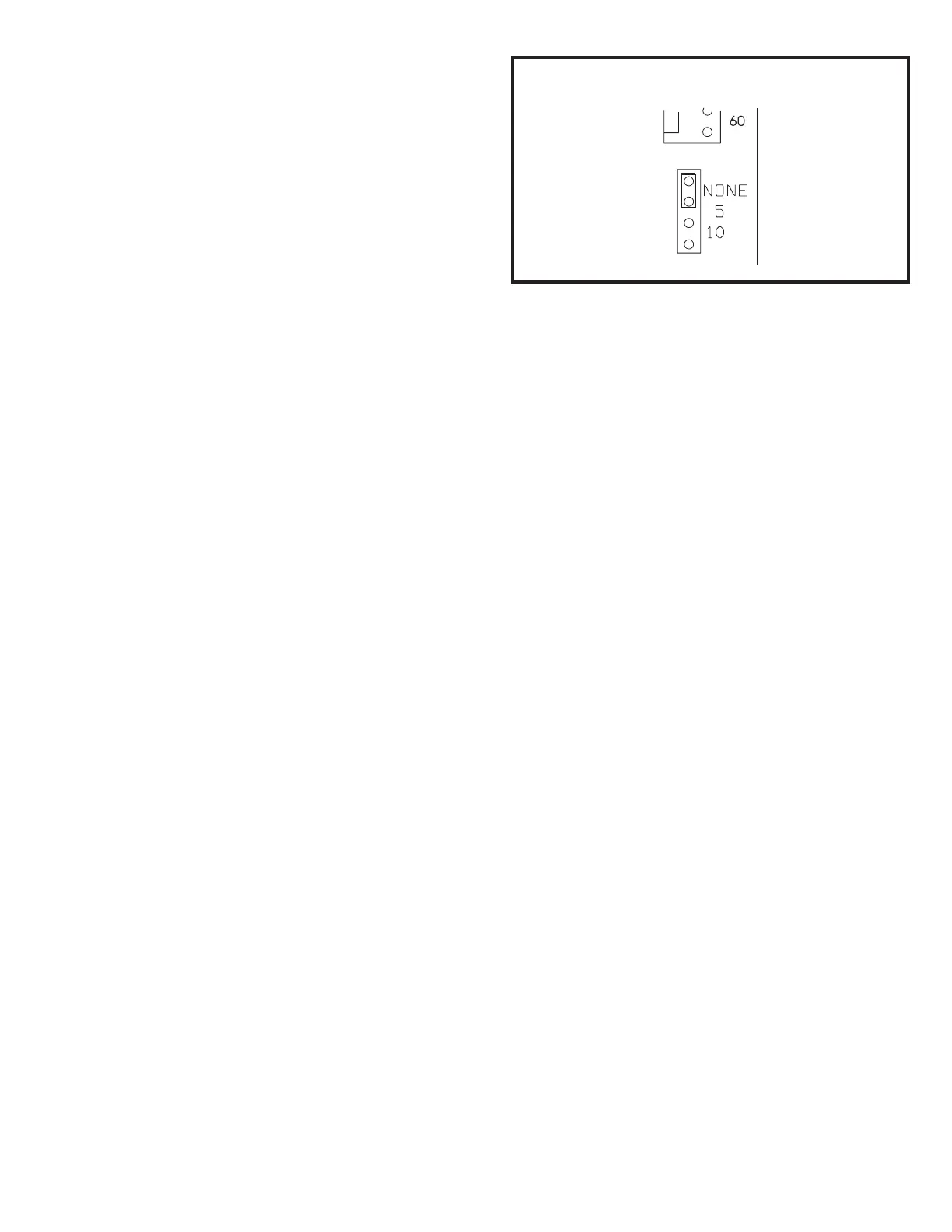
Single Stage Thermostat Operation
(G2D80CR and G2D80CT Models Only)
The automatic heat staging option allows a single stage
thermostat to be used with two stage furnace models
(G2D80CR or G2D80CT). To activate this option, move the
jumper pin (see Figure 23) to desired setting (5 minutes or
10 minutes). The furnace will start on 1
st
stage heat and stay
at 1
st
stage heat for the duration of the selected time before
switching to 2
nd
stage heat.
W1 on the control board must be connected to W1 on the
thermostat.
Humidifier
Terminals are provided on the integrated ignition/blower
control board for connection to a 120-volt humidifier. The
“HUM” terminal is energized whenever the thermostat
calls for heat. See the furnace wiring diagram for specific
connection information.
Electronic Air Cleaner
Terminals are provided on the integrated ignition/blower
control board for connection of a 120-volt electronic air
cleaner. The “EAC” terminal is energized whenever the
thermostat calls for heat, cooling, or continuous blower. See
furnace wiring diagram for specific connection information.
Continuous Blower Operation
The comfort level of the living space can be enhanced when
using this feature by allowing continuous circulation of air
between calls for cooling or heating.
If continuous blower operation on low speed is desired,
connect the lowest speed motor tap to the “CONT” terminal
on the integrated ignition/blower control board (refer to the
furnace wiring diagram.) The blower will operate on low
speed whenever main power is connected to the furnace,
except when it operates on heating or cooling speed during
thermostat call for heat or cooling. This constant air
terminal is intended for low speed only. If a motor is
wired for a higher speed, the increased amp draw could
cause the board control to fail and void the warranty.
Twinning
The integrated ignition/blower control board is designed to
permit “twinning” of furnaces (two furnaces connected to a
common supply and return air system, and controlled by
one thermostat).
When “twinning” two furnaces, each furnace must
have its own dedicated vent system.
G1D80BR and G1D80BT Models – To twin two G1D80BR
or G1D80BT model furnaces, an accessory kit must be
ordered from the manufacturer (see Accessories on page
27). Specific wiring and operating instructions are included
with the kit.
Automatic Heat Staging Jumper
Figure 23
 Loading...