506303-01 Page 11 of 40Issue 0938
For horizontal venting in situations where clearance to floor
joists is limited, see Horizontal Venting – Low Clearance
Installations on page 15.
Upflow Direct Vent Installation
An inlet air restrictor plate (see Figure 2 on page 6) is
supplied with this furnace and can be found in the plastic
bag containing these Installation Instructions and the User’s
Information Manual. This restrictor plate is to be used
only in non-direct vent applications. See page 5 for more
information on installing the restrictor plate in non-direct vent
applications.
The flue pipe screen (see Figure 2 on page 6) should be
installed at the termination of the flue pipe and is designed
to keep objects out of the flue pipe. An additional screen
should not be placed in the intake termination. If a screen
is installed, the air intake may freeze shut.
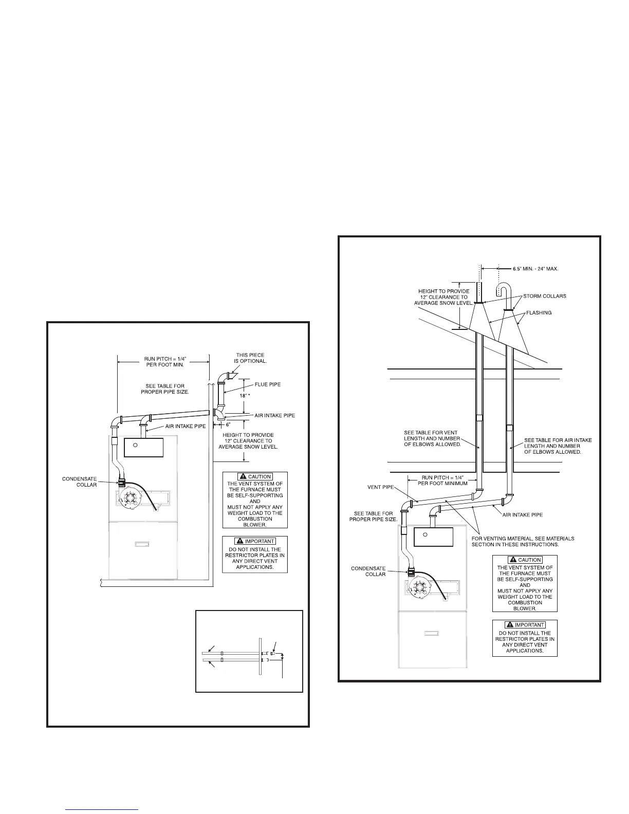
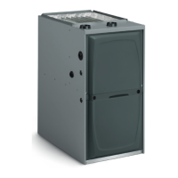
For horizontal venting, refer to Figure 7. For vertical venting,
refer to Figure 8. It is permissible to run the vent vertically
through the roof and terminate it as shown in Figure 8, and
to run the combustion air intake pipe horizontally through a
side wall and terminate as shown in Figure 7. The vent pipe
on horizontal runs must slope upward, away from the furnace,
at a minimum pitch of 1/4" per foot of run, to prevent
accumulation of condensate.
Do not cement air intake into the connector on burner
box. Use high temperature RTV silicone sealant so
intake pipe can be removed if service is required.
In horizontal venting applications, the vent and air intake
pipe must be installed on the same side of the house
within the parameters shown in Figure 7.
Figure 7
Upflow Direct Vent – Horizontal Venting
* Maintaining a vertical separation
between the flue outlet and the air
intake of at least 18” is highly
recommended to minimize the
chance of flue gasses recirculating
and freezing in the air intake pipe.
This distance may be reduced in
milder climates or where wind is
unlikely to blow flue products to the
intake pipe, but should not be less
than 6”.
THIS PIECE
IS OPTIONAL.
INTAKE PIPE
FLUE PIPE
3” MIN. - 48” MAX.
Overhead View
Upflow Direct Vent – Vertical Venting
Figure 8