506303-01
Page 18 of 40 Issue 0938
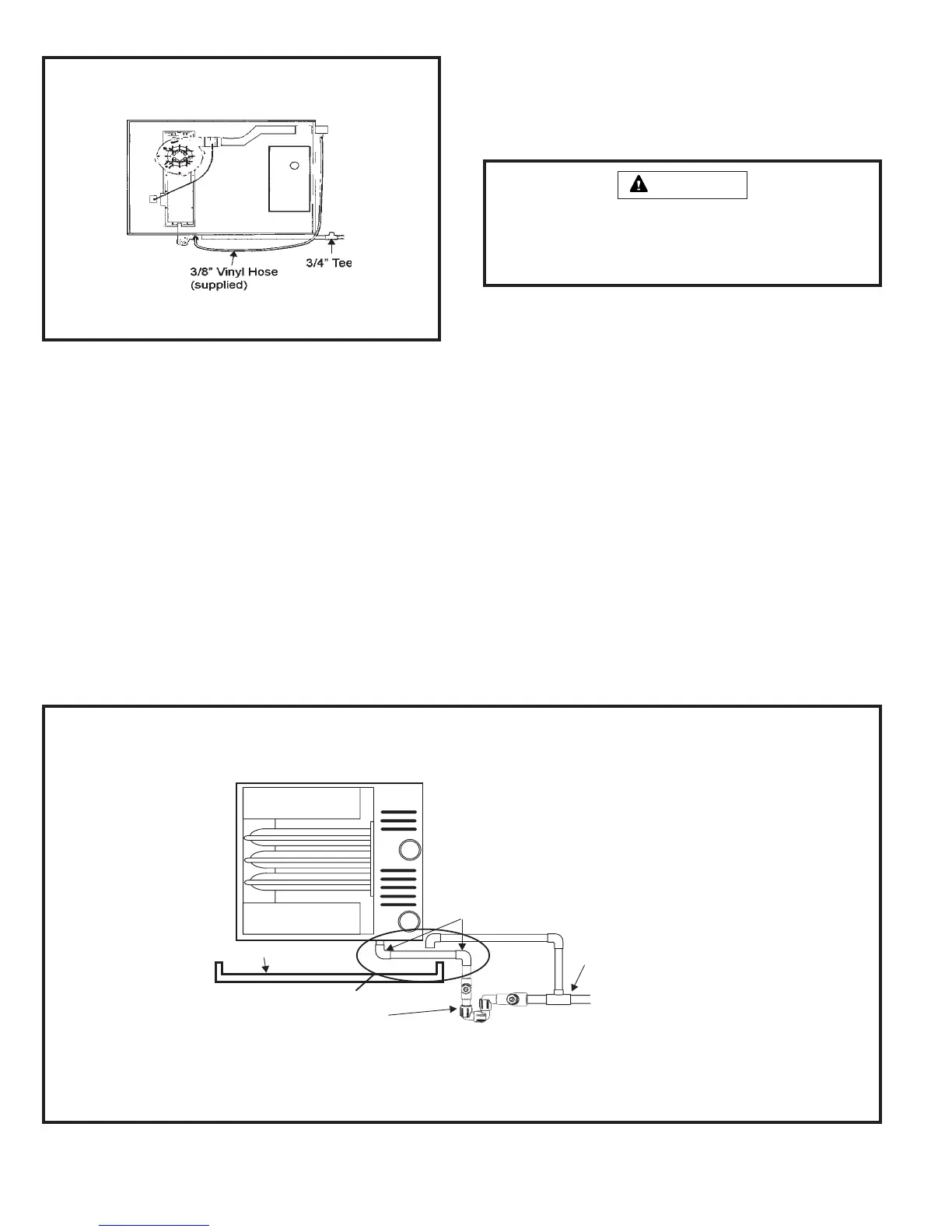
5. Install 3/4" tee (supplied) as shown in Figure 25.
6. From the tee, connect the drain to disposal area. The
top of the tee must be left open for proper condensate
drainage. The open end of the tee must be oriented so
that condensate does not run out of the opening.
7. Connect one end of 72" vinyl hose (supplied) to 3/8"
barbed fitting of the 2" x 2" x 1/2" tee in vent and the other
end to 3/8" barbed fitting on drain trap assembly.
Horizontal Installation – Tight Clearance Below Unit
In certain horizontal installations, clearance between unit and
drain pan beneath unit may be limited. In these applications,
an alternate method may be used to install the condensate
drain trap assembly. Using two 90° elbows (field supplied),
bring condensate trap out to side of unit beyond drain pan
(see Figure 26). After trap assembly has been attached using
this method, follow proper instructions on the previous pages
for completing condensate drain installation.
Drain Pressure Switch Connection
(for G2D93CT and G2D95CT multi-position units only. The
G2D93CU and G2D95CU dedicated upflow units do not
require a drain switch).
Upflow Installation
The G2D93CT and G2D95CT units are shipped from the
manufacturer with a black hose having one end connected to
the 0.10” drain pressure switch and the other end shipped
loose. FOR UPFLOW INSTALLATIONS the loose end is to
be connected to the capped tee in the hose assembly
leading from the primary pressure switch to the inducer.
Remove and discard the plastic cap from the tee and
connect the hose from the 0.10” drain pressure switch to
the tee. (See Figure 31.)
Figure 26
Condensate Drain Trap Installation – Tight Clearance Below Unit
Drain Pan
Two 3/4" 90° Elbows
1/2" NPT x 1/2" PVC
Adapter and Trap Assembly
(supplied)
End View
Field-Supplied Fittings
IMPORTANT: If vent tee is not located over the
auxiliary drain pan, it must be extended over the
pan with an elbow facing down to prevent
overflow in the event of a blocked drain. The
elbow must be installed downward over the
auxiliary pan to prevent wicking back down the
condensate line.
Do not install trap assembly any farther than 10" from unit. The pressure switch and vent
hoses must be able to reach the barbed fittings on the trap assembly.
NOTE: Vent tee to avoid
vapor lock. If connecting
to waste drain pipe, a
second trap must be
installed downstream.
Figure 25
Completing Condensate
Drain Installation
Be sure to avoid double-trapping the vinyl hose. Hose must
be installed as shown.
To avoid property damage caused by condensate drain
blockage, install a field-fabricated auxiliary drain pan with
a separate drain line to the outside under the entire furnace
and drain system, including open vent tees.
CAUTION