506303-01 Page 19 of 40Issue 0938
Be sure that the pressure switch hose does not form a
trap to hold condensation that could form from the flue
gas. Hose may be cut shorter to avoid forming a trap, if
required.
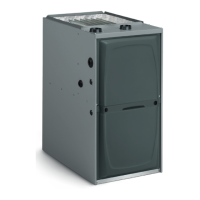
Horizontal Installation
The G2D93CT and G2D95CT units are shipped from the
manufacturer with a black hose having one end connected
to the 0.10” drain pressure switch and the other end shipped
loose. FOR HORIZONTAL INSTALLATIONS the loose end
MUST be connected to the external drain trap.
Route hose through gas line access hole in cabinet. Then
connect to 1/4" barbed fitting on drain trap assembly.
For right to left airflow installations, see Figure 28. For left
to right airflow installations, see Figure 29.
Be sure that the pressure switch hose does not form a
trap to hold condensation that could form from the flue
gas. Hose may be cut shorter to avoid forming a trap, if
required.
Circulating Air Supply
When the furnace is installed so that the supply ducts carry
air circulated by the furnace to areas outside the space
containing the furnace, the return air shall be handled by a
duct or ducts sealed to the furnace casing and terminated
outside the space containing the furnace.
When an air conditioning unit is used in conjunction
with the furnace, the evaporator coil must be installed
in the discharge (supply) air. Do not install an evaporator
coil in the return air; excessive condensation will occur
within the furnace.
CAUTION
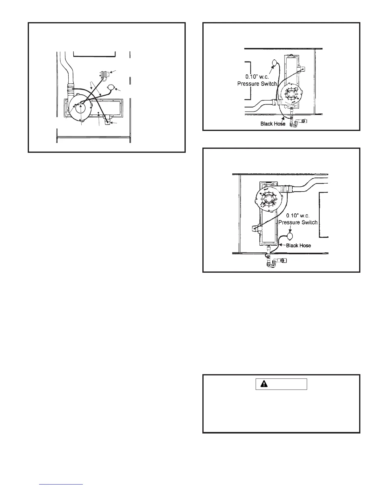
Pressure Switch Connection
Horizontal Installation – R to L Airflow
Figure 28
Pressure Switch Connection
Upflow Installation
Figure 27
Black
Hoses
Tee
(supplied)
Low Fire-High Fire
Pressure Switch
Assembly
Yellow Cap
Blower
Housing
Tap
Trap
0.10” w.c.
Pressure Switch
Pressure Switch Connection
Horizontal Installation – L to R Airflow
Figure 29
A return air duct system is recommended. If the unit is
installed in a confined space or closet, a return connection
must be run, full size, to a location outside the closet. The
air duct in the closet must be tight to prevent any entrance
of air from the closet into the circulating air.
If there is no complete return air duct system, the return air
connection must be sealed to the furnace casing and run, full
size, to a location outside the utility room or space housing the
furnace to prevent a negative pressure on the venting system.