506303-01
Page 20 of 40 Issue 0938
3. With the filter access opening toward the front of the
furnace, use sheet metal screws to fasten the rack(s)
to the side panel(s).
The filter slides in the rack from the front of the unit. Install
the filter(s) with the mesh side towards furnace.
Model #AFILTHA7 single side filter frame kit is available for
single side return air connection in installations requiring more
than 1600 CFM nominal air delivery. A bottom return filter kit
(model #AFILT529) is also available from the manufacturer.
Outlet Duct
For installations not equipped with a cooling coil, a
removable access panel must be provided in the outlet duct.
The opening should be accessible when the furnace is
placed in service. Smoke or reflected light may be observed
inside the casing to indicate the presence of leaks in the
heat exchanger. The cover for the opening shall be attached
in such a manner as to prevent leaks. The recommended
opening size is 6" x 14" for all sizes.
Filters
If a filter other than one supplied by the furnace manufacturer
is used, it must be sized according to information provided
in Table 3.
A filter rack and cleanable 16" x 25" x 1/2" filter are supplied
with the furnace. (Models designed for more than 1600 CFM
nominal air delivery include two of each.) The filter rack is
to be installed between the return air duct and the side of
the furnace.
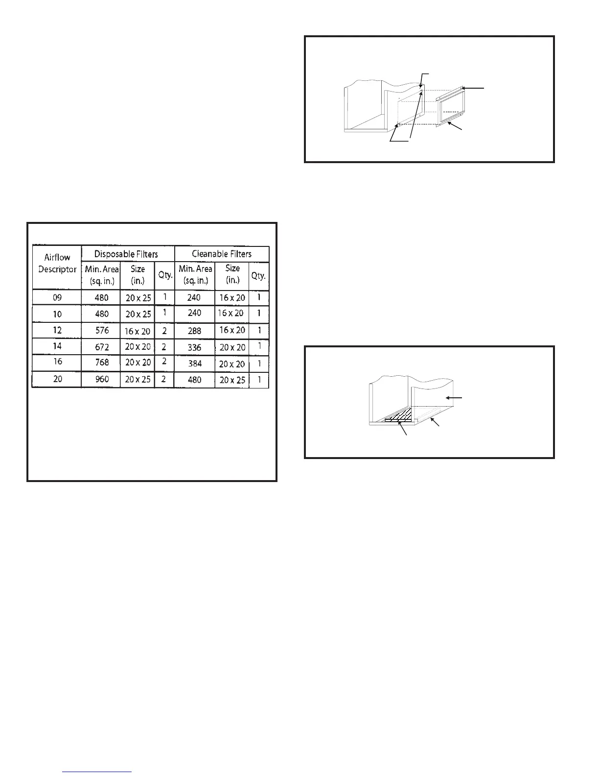
Refer to Figure 30 and the following instructions to install
the filter rack:
1. Using the corner embossments as a guide, mark and
cut a full-size opening in the side panel(s).
2. Using the filter rack as a template, mark and drill four
7/64” diameter screw holes in the side panel(s).
Other filter accessories are also available from the
manufacturer including a full line of indoor air quality products.
For information on these products, contact the local distributor.
Gas Supply and Piping
Refer to the furnace rating plate to make sure the furnace
is equipped to burn the gas supplied (natural or propane).
Gas supply piping should be installed in accordance with local
codes and the regulations of the utility. Piping must be of
adequate size to prevent undue pressure drop. Consult the
local utility or gas supplier for complete details on special
requirements for sizing gas piping.
Table 3
Minimum Filter Requirements
1. The Airflow Descriptor is the two digits following the “D”
(example: G2D93CT080D16C) or “V” (example:
G2D95CT080V16C) in the model number.
2. Areas and dimensions shown for cleanable filters are based on
filters rated at 600 feet per minute face velocity.
3. Typical filter sizes are shown; however, any combination of
filters whose area equals or exceeds the minimum area shown
is satisfactory.
Filter Rack Mounting Hole
Screw
Filter Rack
Corner Embossments
Front of Cabinet
Filter Rack Installation
Figure 30
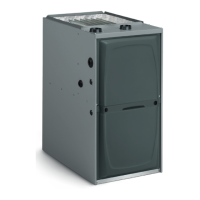
Figure 31
Bottom Filter Location
Filter
Base
Side