506303-01
Page 22 of 40 Issue 0938
The furnace must be grounded and wired in accordance
with local codes or, in the absence of local codes, with the
National Electrical Code ANSI/NFPA No. 70 (latest edition)
and/or CSA C22.1 Electrical Code (latest edition) if an
external electrical source is utilized.
In all instances, other than wiring for thermostat, the wiring to
be done and any replacement of wire shall conform with the
temperature limitation for Type T wire – 63°F (35°C) rise.
Connect a sufficiently sized wire with ground to the furnace’s
line voltage connections and ground lug. Refer to the furnace
rating plate for electrical characteristics to be used in sizing
field supply wiring and over-current protection.
The line voltage supply should be routed through a readily
accessible disconnect located within sight of the furnace.
A junction box on the furnace side panel is provided for
line voltage connections. Refer to the furnace wiring
diagram for specific connection information.
Proper polarity of the supply connections (“HOT” and
“NEUTRAL”) must be observed to ensure that safety
controls provide the protection intended.
A connection to the ground lug and actual earth ground
(typically a ground stake or buried steel pipe) must be
maintained for proper operation.
Thermostat
Install a room thermostat according to the instructions
furnished with it. Select a location on an inside wall that is
not subject to drafts, direct sunshine, or other heat sources.
The initial heat anticipator setting should be equal to the
total current draw of the control circuit.
Low voltage thermostat connections are to be made to the
integrated ignition/blower control board as indicated on the
wiring diagram.
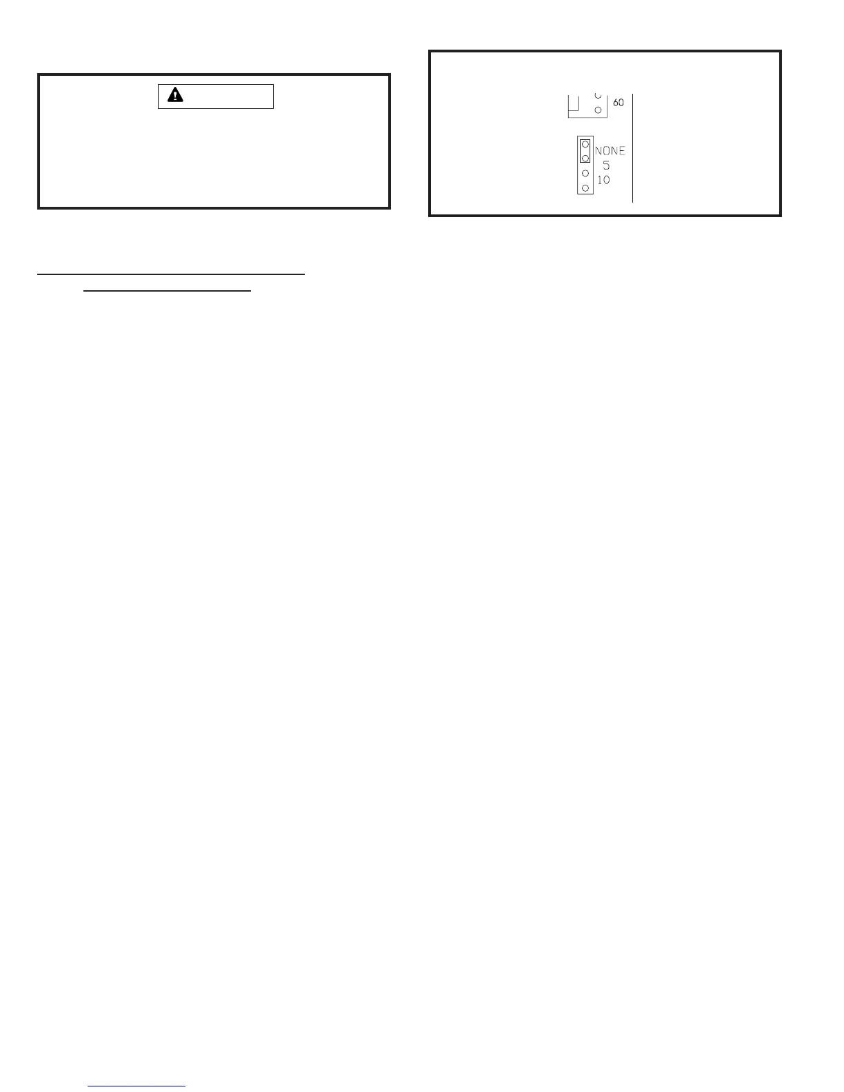
Single Stage Thermostat Operation
The automatic heat staging option allows a single stage
thermostat to be used with a two stage furnace. To activate
this option, move the jumper pin (see Figure 33) to desired
setting (5 minutes or 10 minutes). The furnace will start on 1
st
Electrical Wiring
stage heat and stay at 1
st
stage heat for the duration of the
selected time before switching to 2
nd
stage heat.
W1 on the control board must be connected to W1 on the
thermostat.
Humidifier
Terminals are provided on the integrated ignition/blower control
board for connection to a 120-volt humidifier. The “HUM”
terminal is energized whenever the thermostat calls for heat.
Refer to furnace wiring diagram for specific connection
information.
Electronic Air Cleaner
Terminals are provided on the integrated ignition/blower control
board for connection of a 120-volt electronic air cleaner. The
“EAC” terminal is energized whenever the thermostat calls
for heat, cooling, or continuous blower. Refer to the furnace
wiring diagram for specific connection information.
Continuous Blower Operation (G2D93CT/U Models)
The comfort level of the living space can be enhanced when
using this feature by allowing continuous circulation of air
between calls for cooling or heating.
If continuous blower operation on low speed is desired,
connect the lowest speed motor tap to the “CONT” terminal
on the integrated ignition/blower control board (refer to the
furnace wiring diagram). The blower will operate on low
speed whenever main power is connected to the furnace,
except when it operates on heating or cooling speed during
thermostat call for heat or cooling. This constant air
terminal is intended for low speed only. If a motor is
wired for a higher speed, the increased amp draw could
cause the board control to fail and void the warranty.
Risk of electrical shock. Disconnect electrical power at
the circuit breaker or service panel before making
electrical connections. Failure to disconnect power
supplies can result in property damage, personal injury,
or death.
WARNING
Automatic Heat Staging Jumper
Figure 33
 Loading...