506303-01
Page 24 of 40 Issue 0938
Soft Stop
At the end of a cooling or heating cycle, the variable speed
motor will slowly ramp down after a short blower “off” delay.
If continuous blower operation has been selected, the
variable speed motor will slowly ramp down until it reaches
the airflow for that mode.
Passive and Active Dehumidification
Passive Dehumidification
For situations where humidity control is a problem, a
dehumidification feature has been built into the variable
speed motor. At the start of each cooling cycle, the variable
speed motor will run at 82% of the rated airflow for 7.5
minutes. After 7.5 minutes has elapsed, the motor will
increase to 100% of the rated airflow.
Active Dehumidification
To achieve additional dehumidification, clip the jumper wire
located below the DEHUM terminal on the integrated ignition/
blower control board and connect a humidity control that
opens on humidity rise to the DEHUM and R terminals. The
DEHUM terminal on the control board must be connected to
the normally closed contact of the humidity control so that the
board senses an open circuit on high humidity. In this setup,
the variable speed motor will operate at a 18% reduction in
the normal cooling airflow rate when there is a call for
dehumidification.
Both the passive and active dehumidification methods
described above can be utilized on the same furnace.
Circulating Airflow Adjustments
Cooling Mode
The units are factory set for the highest airflow for each model.
Adjustments can be made to the cooling airflow by
repositioning the jumper plug marked COOL – A, B, C, D
(see Figure 36) based on the information found in the table.
To determine what CFM the motor is delivering at any time,
count the number of times the amber LED on the control
board flashes. Each flash signifies 100 CFM; count the flashes
and multiply by 100 to determine the actual CFM delivered
(for example: 10 flashes x 100 = 1000 CFM).
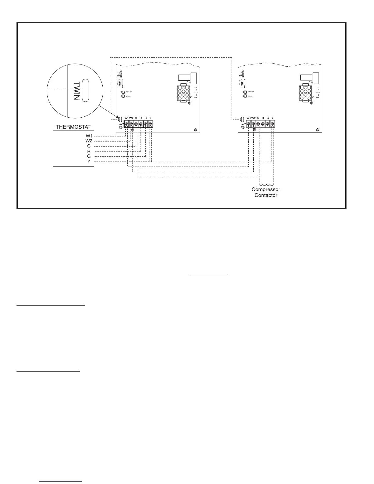
Figure 35
Wiring Connections for Twinning Two G2D93CT/U Furnaces
Two Stage Heating/Single Stage Cooling