506303-01 Page 25 of 40Issue 0938
Heating Mode
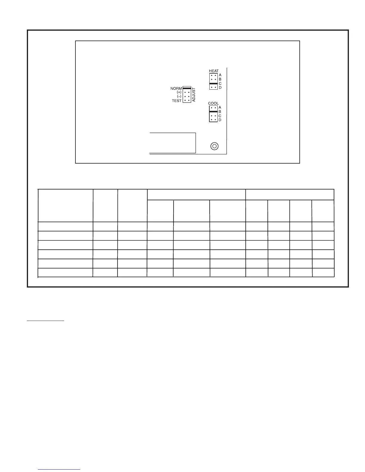
The unit as shipped is factory set to run at the middle of the
heating rise range as shown on the unit rating plate. If higher
or lower rise is desired, change the airflow 15% up or down
by moving the ADJUST jumper plug (see Figure 36) from
the NORM position to the (+) or (–) position. This adjustment
will also cause the cooling airflow to be raised or lowered
by 15%.
The TEST position on the ADJUST tap is not used.
The jumper plug on the HEAT tap should remain in the
position (A, B, C, or D) listed in the HEAT Setting column in
the table found in Figure 36. Changing the setpoints may
not increase or decrease heating blower speeds. In some
cases, running the blower with the heat settings in the wrong
position may cause the furnace to operate outside the
furnace’s intended temperature rise range.
Figure 36
Adjusting Airflow – G2D95CT/U Models Only
ADJUST, HEAT, and COOL Taps
on Integrated Ignition/Blower Control Board
A
1
Model
Motor
HP
ADJUST
Setting
HEAT
Setting
High Fire
Low Fire
COOL
Setting
A
COOL
Setting
B
COOL
Setting
C
COOL
Setting
D
Heating CFM @ .50 Static
Cooling CFM @ .50 Static
G2D95CT/U040V12
G2D95CT/U060V14
G2D95CT/U080V16
G2D95CT/U080V20
G2D95CT/U100V20
G2D95CT/U125V20
1/2
1/2
3/4
1
1
NORM
NORM
NORM
NORM
NORM
NORM
A
A
A
C, D
B
750
1000
1500
1500
1700
2100
500
650
950
950
1150
1450
1200
1400
1600
2000
2000
2000
1000
1200
1400
1800
1800
1800
800
1000
1200
1600
1600
1600
600
800
1000
1400
1400
1400