506303-01 Page 29 of 40Issue 0938
Heat Pump
For heat pump operation, clip the jumper wire located below
the O terminal on the integrated ignition/blower control board.
In heat pump mode, a call for heat pump operation follows the
same sequence as a call for cooling with the exception that
there is a 30-second blower ramp up to blower CFM.
Controls
Following is a description of the operation of some of the
controls used in this furnace. All models use one of each
control, except as noted.
Pressure Switch
The pressure switch is a normally open switch that monitors
combustion air flow. Inadequate air flow resulting from
excessive venting system restriction, a failed combustion
blower, or a blocked drain will cause the switch to remain
open.
Rollout Switch
The rollout switch is a normally closed switch that opens
when abnormal temperatures exist in the burner area. This
can be caused by a restricted heat exchanger causing the
burner flame to “roll out” into the vestibule area or burner
box. These units have two rollout switches. This switch
must be manually reset by pushing the button on top to
restore furnace operation.
Primary Limit Control
This is a normally closed control that opens if abnormally
high circulating air temperatures occur. It is an automatic
reset control.
If the active dehumidification feature is enabled, the
circulating blower runs at 82% of the selected cooling speed
as long as there is a call for dehumidification.
Two Stage Cooling (see Figure 41)
A call for 1
st
stage cooling from the thermostat closes the R
to Y circuit on the control board. The control waits for a 1-
second delay before energizing the circulating blower. The
blower motor runs at 57% of the selected air flow for the
first 7.5 minutes of the 1
st
stage cooling demand (passive
dehumidification mode). After 7.5 minutes, the blower motor
runs at 70% of the selected cooling air flow until 1
st
stage
cooling demand is satisfied.
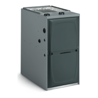
A call for 2
nd
stage cooling from the thermostat closes the R to
Y2 circuit on the control board. The blower motor ramps up to
100% of the selected cooling air flow. When the demand for
cooling is met, the blower ramps down to Y1 until satisfied, then
ramps down to 57% for 1 minute, then turns off.
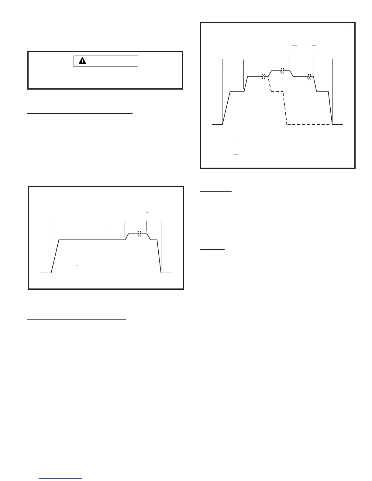
Single Stage Cooling (see Figure 40)
A call for cooling from the thermostat closes the R to Y circuit
on the integrated ignition/blower control board. The control
waits for a 1-second delay before energizing the circulating
blower to 82% of the selected cooling CFM (passive
dehumidification mode). After 7.5 minutes, the circulating
blower automatically ramps up to 100% of the selected
cooling airflow. When the call for cooling is satisfied, the
circulating blower ramps back down to 82% of the selected
cooling airflow for 1 minute, then shuts off.
The system must not be in either the passive or active
dehumidification mode when charging a cooling system.
IMPORTANT
7.5 minutes
Y
y
82%
100%
82%
1
min
CALL OFF
Y - Cool Demand Present
- Cool Demand Satisfied
y
Single Stage Cooling
(G2D95CT/U Models)
Figure 40
Two Stage Cooling
(G2D95CT/U Models)
Figure 41
Y1
y1
57%
100%
CALL OFF
7.5
minutes
70%
Y1 - 1 Stage Cool Demand Present
st
- Demand Satisfied1 Stage Cool
st
y1
Y2 - 2 Stage Cool Demand Present
nd
- 2 Demand Satisfied
nd
Stage Cool
y2
1
min
70%
Y1
y2
/
Y1
/
Y2
y1
57%
1
min
57%
 Loading...