506303-01
Page 30 of 40 Issue 0938
Auxiliary Limit Control
This is a normally closed control that opens under abnormal
“reverse air flow” conditions that could occur in a counterflow
or horizontal installation if the circulating blower fails. It is
an automatic reset control.
G2D93CU and G2D95CU models do not include an auxiliary
limit control.
Interlock (Blower Door) Switch
When the blower door is removed, the interlock switch
breaks the power supply to the burner controls and blower
motor. The switch operation must be checked to confirm it
is operating correctly.
System Sentry™ Integrated Ignition/Blower Control Board
The System Sentry™ integrated ignition/blower control board
operates all functions of the furnace and the accessories
connected to it.
G2D93CT/U models feature user-selectable blower “off”
delay times (60, 90, 120, and 180 seconds) that are factory
set to provide a 120-second blower “off” delay on heating
(see wiring diagram on page 35).
Refer to the furnace wiring diagram while using the following
procedure to the change motor speed on a G2D93CT/U
furnace:
1. Turn off electrical power to the unit.
2. Connect the desired speed tap for cooling on the
integrated ignition/blower control board.
3. For heating speed, check the temperature rise and, if
necessary, adjust the blower speed tap to maintain
temperature rise within the range shown on the furnace
rating plate.
To use the same speed tap for both heating and cooling,
install a piggyback terminal on the speed tap using a
short jumper. Wire 1/4" quick connect terminals on both
ends to jumper the “HEAT” and “COOL” speed on the
integrated ignition/blower control board.
4. The remaining speed taps must be connected to dummy
terminals marked “PARK” on the integrated ignition/
blower control board.
Checking and Adjusting Gas Input
The minimum permissible gas supply pressure for the
purpose of input adjustment is 5" W.C. for natural gas or
11" W.C. for propane gas. This furnace requires conversion
for use with propane (see Accessories section on page 35
for correct kit). The maximum inlet gas supply pressure is
10.5" W.C. for natural gas and 13" W.C. for propane. Gas
input must never exceed the value shown on the furnace
rating plate.
These units are rated for outlet (manifold) pressures of 1.7 "
W.C. (1
st
stage) and 3.5" W.C. (2
nd
stage) for natural gas. When
these furnaces have been converted for use with propane
gas, the outlet pressures are 4.9" W.C. (1
st
stage) and 10.0"
W.C. (2
nd
stage).
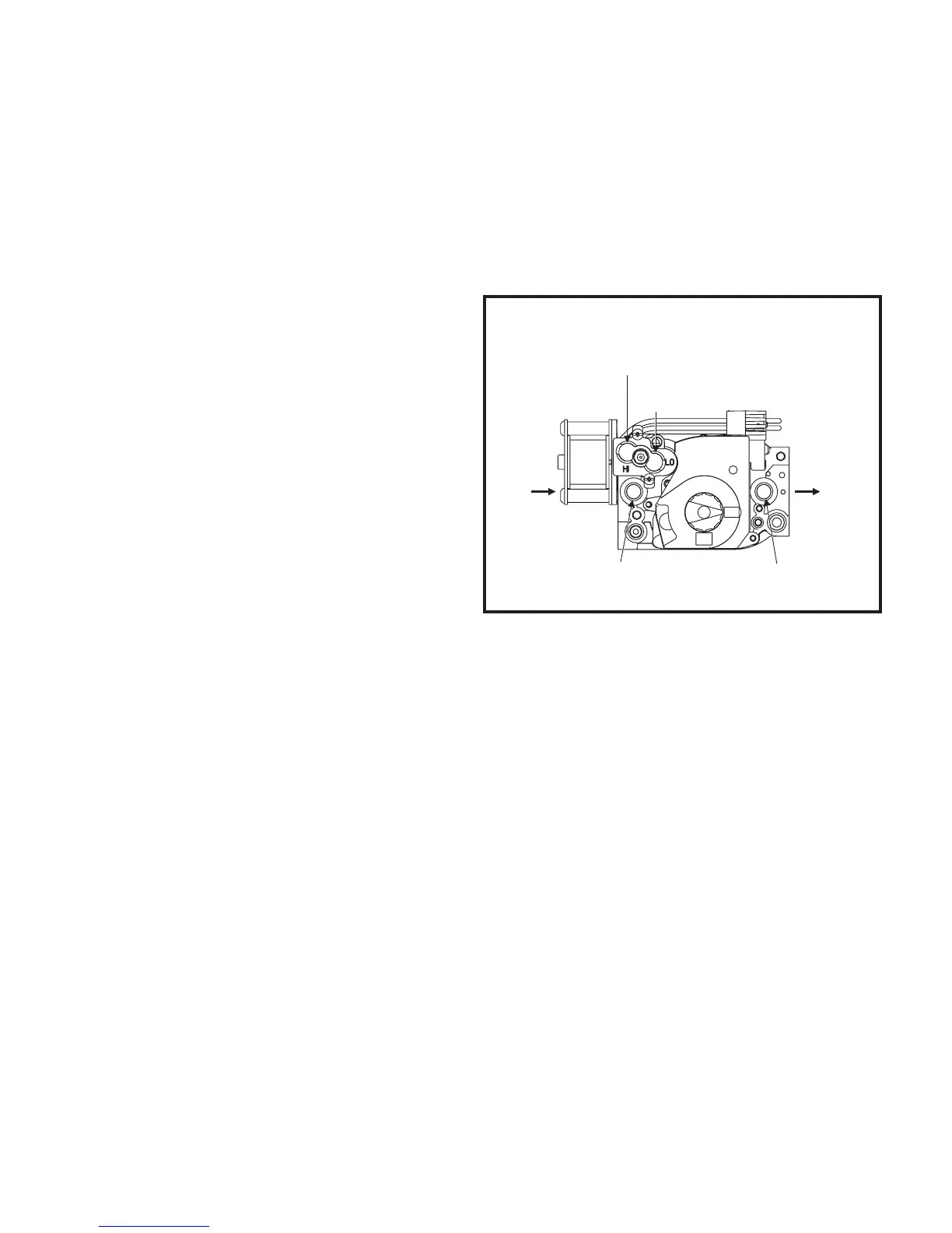
To measure inlet or outlet pressure, remove plug from
desired pressure tap (inlet or outlet) as shown in Figure 42
and connect a water manometer or gauge to the proper
pressure tap.
These models have separate adjusting screws (3/32" hex)
for 1
st
stage (marked “LO”) and 2
nd
stage (marked “HI”). The
adjusting screws are positioned on either side of the barbed
fitting (see Figure 42). Turn the adjusting screws clockwise to
increase pressure and input; counterclockwise to decrease
pressure and input. The pressure regulator adjustment is
sensitive; one turn of the adjusting screw will result in a
relatively large change in manifold pressure.
To adjust the regulator:
1. Set high-fire (2
nd
stage) setting by turning hex
adjustment screw to desired rate.
2. Set low-fire (1
st
stage) setting by turning hex adjustment
screw to desired rate.
Make sure the final high- and low-fire manifold
pressures are within the allowable ranges specified
above for the gas being used.
Checking and Adjusting Gas Input
Figure 42
OFF
ON
Inlet Pressure Tap
1/8" NPT
Outlet Pressure Tap
1/8" NPT
High-Fire (2 Stage) Adjustment
Under Vent Cap
nd
Low-Fire (1 Stage) Adjustment
Under Vent Cap
st
 Loading...