506303-01
Page 14 of 40 Issue 0938
Prime the trap system by slowly pouring 1 cup of water down
the vent pipe. On initial start-up of the unit, some of the
water used to prime the trap system may run down into the
combustion blower and cause noise.
Horizontal Non-Direct Vent Installation
An inlet air restrictor plate (see Figure 2 on page 6) is
supplied with this furnace and can be found in the plastic
bag containing these Installation Instructions. This restrictor
plate is to be used only in non-direct vent applications. See
page 5 for more information on installing the restrictor plate
in non-direct vent applications.
Two inlet air restrictor plates are supplied with each furnace
– a 2" plate and a 3" plate. Use the proper restrictor plate
for the furnace model.
The flue pipe screen (see Figure 2 on page 6) should be
installed at the termination of the flue pipe and is designed
to keep objects out of the flue pipe.
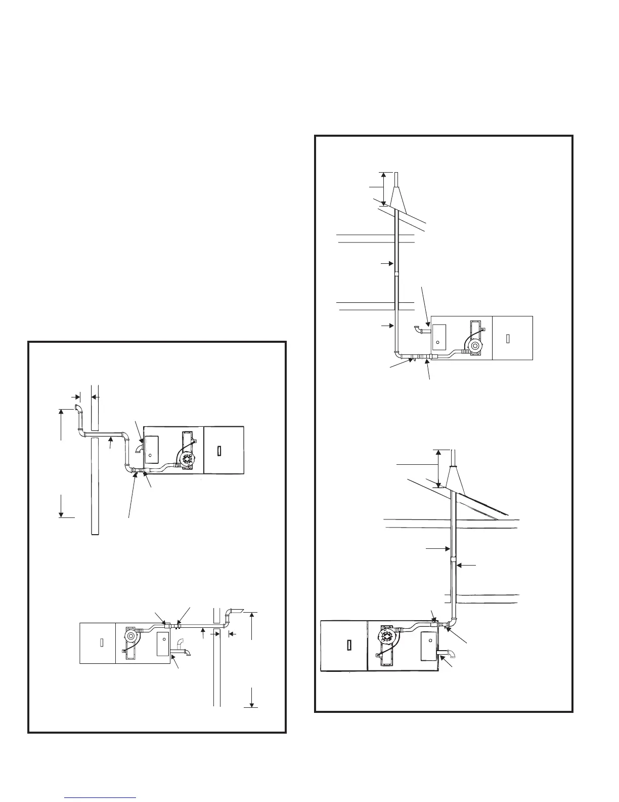
For horizontal venting, refer to Figure 13. For vertical venting,
refer to Figure 14. The vent pipe on horizontal runs must slope
upward, away from the furnace, at a minimum pitch of 1/4" per
foot of run, to prevent accumulation of condensate.
Prime the trap system by slowly pouring 1 cup of water
down the vent pipe. On initial start-up of the unit, some of
the water used to prime the trap system may run down into
the combustion blower and cause noise.
Airflow Left to Right
Figure 13
Horizontal Non-Direct Vent –
Horizontal Venting
* Canadian installations: See “Canadian Applications Only” on page 6.
Drain Tee
(supplied)
Inlet Air Restrictor Plate
(see page
Vent
Pipe
Height to
provide
clearance
to average
snow level
6”
12”
6)
3” Long Piece of
2” Diameter Pipe
(supplied) *
*
Airflow Right to Left
6”
Drain Tee
(supplied with unit)
Inlet Air Restrictor Plate
()see page 6
Vent
Pipe
Height to
provide
clearance
to average
snow level
*
3” Long Piece of
2” Diameter Pipe
(supplied) *
12”
Figure 14
Horizontal Non-Direct Vent –
Vertical Venting
* Canadian installations: See “Canadian Applications Only” on page 6.
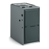
Height to
clearance to
snow level
average
Drain Tee
(supplied)
Inlet Air Restrictor Plate
()see page 6
For venting material,
see venting section
in these instructions.
Vent Pipe
*
provide 12”
3” Long Piece of
2” Diameter Pipe
(supplied) *
Airflow Left to Right
Inlet Air Restrictor Plate
()see page
Vent
Pipe
Height to
provide
clearance
to average
snow level
Drain Tee
(supplied)
See table for
vent length
and number
of elbows
allowed
12”
6
3” Long Piece of 2” Diameter Pipe
(supplied) *
*
Airflow Right to Left