506303-01 Page 15 of 40Issue 0938
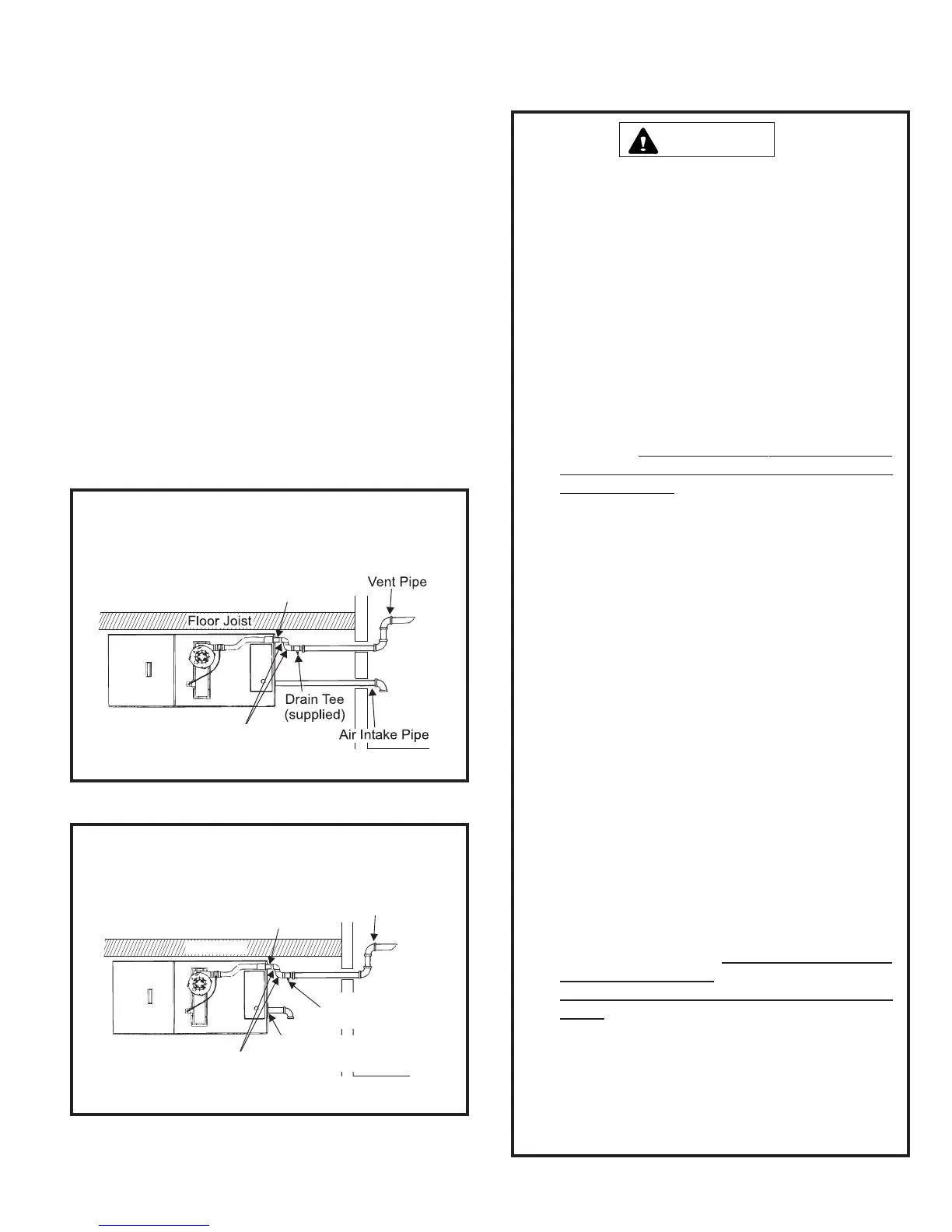
Horizontal Venting – Low Clearance Installations
Vent pipe on horizontal runs must slope upward, away from
the furnace, at a minimum pitch of 1/4" per foot of run, to
prevent accumulation of condensate. In certain horizontal,
left-to-right airflow applications, the furnace’s close proximity
to the floor joists above the unit may make it difficult to obtain
the required pitch/slope. Figures 15 and 16 show the accepted
vent practice to obtain proper pitch/slope back to furnace for
proper drainage. For direct vent applications, see Figure 15.
For non-direct applications, see Figure 16.
In all applications, minimum clearances to combustibles
must be observed (as shown in Table 1 on page 4) as well
as all other required clearances shown in Figures 11 and
13 on pages 13 and 14.
Existing Venting Systems
When an existing furnace is removed or replaced, the original
venting system may no longer be sized to properly vent the
attached appliances. An improperly sized venting system can
result in spillage of flue products into the living space, the
formation of condensate, leakage, etc. See the WARNING
box below for proper test procedure.
Failure to follow the steps outlined below for each
appliance connected to the venting system being
placed into operation could result in carbon monoxide
poisoning or death.
The following steps shall be followed for each appliance
connected to the venting system being placed into
operation, while all other appliances connected to the
common venting system are not in operation:
1. Seal any unused openings in the common venting
system.
2. Visually inspect the venting system for proper size
and horizontal pitch, as required in the National Fuel
Gas Code,
ANSI Z223.1/NFPA 54 (latest edition)
or the CSA B149.1, Natural Gas and Propane
Installation Codes and these instructions. Determine
that there is no blockage or restriction, leakage,
corrosion, or other deficiencies which could cause
an unsafe condition.
3. As far as practical, close all building doors and
windows between the space in which the
appliance(s) connected to the venting system are
located and other spaces in the building.
4. Close fireplace dampers.
5. Turn on clothes dryers and any appliance not
connected to the venting system. Turn on any
exhaust fans, such as range hoods and bathroom
exhausts, so they are operating at maximum speed.
Do not operate a summer exhaust fan.
6. Follow the lighting instructions. Place the unit being
inspected in operation. Adjust the thermostat so
appliance is operating continuously.
7. Test for spillage from draft hood equipped
appliances at the draft hood relief opening after 5
minutes of main burner operation. Use the flame of
a match or candle.
8. If improper venting is observed during any of the
above tests, the venting system must be corrected
in accordance with the National Fuel Gas Code,
ANSI Z223.1/NFPA 54 (latest edition) and/or the
CSA B149.1, Natural Gas and Propane Installation
Codes.
9. After it has been determined that each appliance
remaining connected to the venting system properly
vents when tested as outlined above, return doors,
windows, exhaust fans, fireplace dampers, and any
other gas-fired burning appliance to their previous
conditions of use.
CARBON MONOXIDE POISONING HAZARD
WARNING
Figure 15
Horizontal Direct Vent – Horizontal Venting
Low Clearance Installation
3” Long Piece of
2” Diameter Pipe
(supplied) *
2 - 2” 90° Elbows
*
* Canadian installations: See “Canadian Applications Only” on page 6.
Floor Joist
Vent Pipe
Drain Tee
(supplied) *
Inlet Air Restrictor Plate
(see page 6)
3” Long Piece of
2” Diameter Pipe
(supplied) *
2 - 2” 90° Elbows
Figure 16
Horizontal Non-Direct Vent – Horizontal Venting
Low Clearance Installation
* Canadian installations: See “Canadian Applications Only” on page 6.
 Loading...