506303-01
Page 16 of 40 Issue 0938
Condensate Disposal Installation
The condensate drain should be routed directly to a locally
acceptable disposal area. The condensate drain line should
not be run directly to the outdoors especially in colder
climates where temperatures may cause the condensate
to freeze in the drain line.
In horizontal installations where clearance beneath the unit
is limited, an alternate method for condensate disposal trap
installation may be used (see Horizontal Installation –
Tight Clearance Below Unit on page 18).
Upflow Installation
Install the condensate drain line to the unit as follows. The
condensate can be drained from either the right or left side
of the furnace. Install the 1/2" NPT x 3/4" PVC adapter
(supplied) in the drain on the side that the draining will occur.
Install the plastic pipe plug opposite of the drain. Using 3/4"
PVC pipe, make a connection from the adapter just installed
to extend just outside the unit. Install a 3/4" PVC tee as
shown in Figure 17. From the tee, install the drain to the
disposal area. The top of the tee must be left open for proper
condensate drainage.
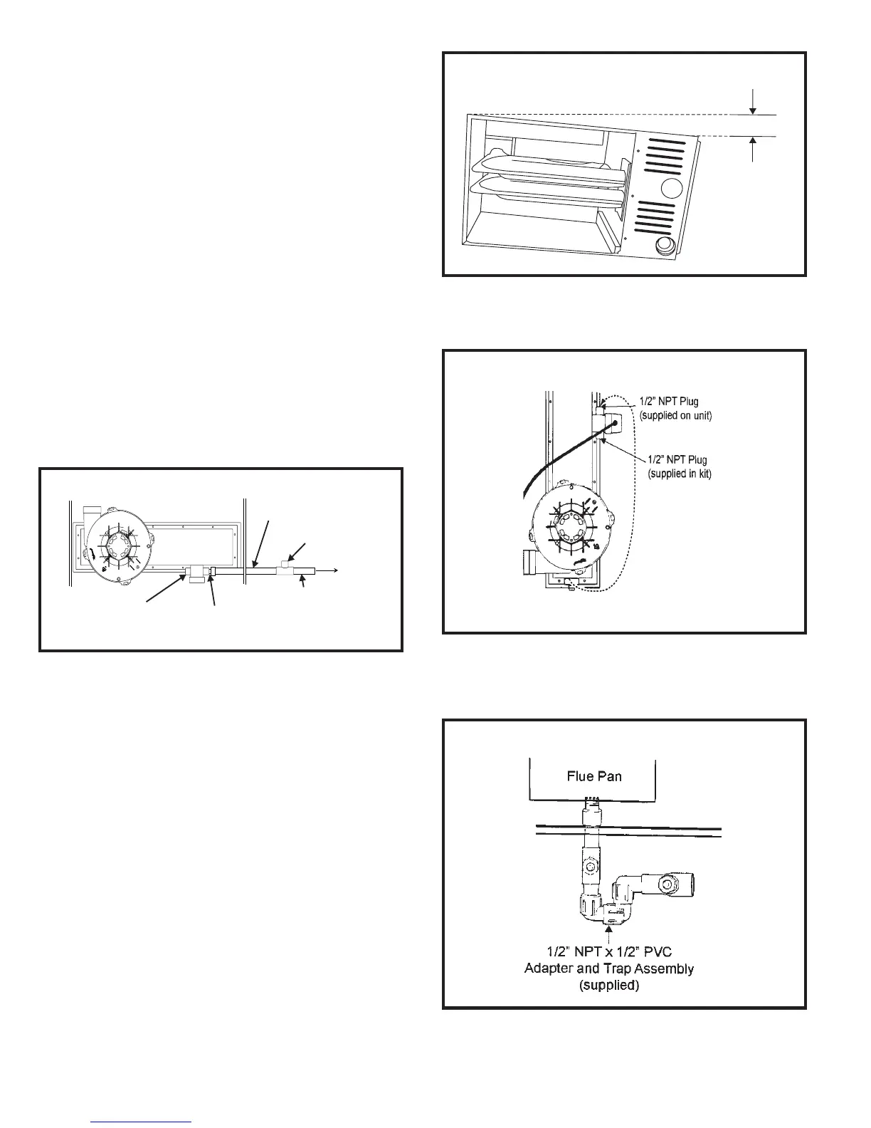
Horizontal Installation – Right to Left Airflow
Furnace must be mounted such that the side through which
the condensate will drain is elevated a minimum of 9" above
a surface such as a floor.
Install unit at a slight pitch forward (see Figure 18).
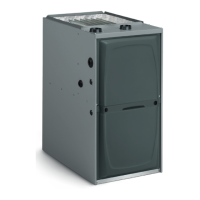
1. Relocate the 1/2" NPT plug installed on the flue pan to
one side of the internal trap assembly (as shown in
Figure 19).
2. Connect the 1/2" NPT plug (supplied) to the opposite
side of the internal trap assembly from the plug installed
in Step 1.
3. Insert trap assembly (supplied) into flue pan (see Figure
20).
Figure 17
Condensate Disposal – Upflow
THRU.
59.69/56.64
1/2” NPT PLUG
(SUPPLIED)
1/2” NPT x 3/4”PVC ADAPTER
(SUPPLIED)
3/4” PVC
TEE MUST REMAIN
OPEN
3/4” PVC
Figure 18
Tilt Unit Forward
1/4" Max
Figure 19
Insert Plugs
Figure 20
Install Trap Assembly