installation &
operating instructions
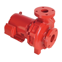
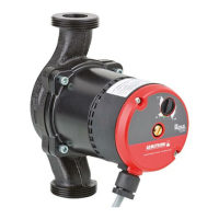
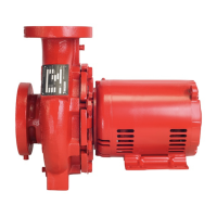
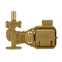
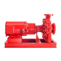
In-line circulating
pumps
5
Input demand
There are two methods of setting the input demand using the
PerfectSpeed® User Interface box.
Table 3 – Input demand options
Input demand
setting method
Definition
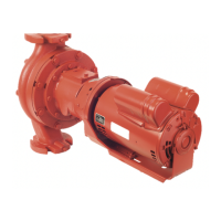
Set with On-Board
Potentiometer
The input demand can be set via the On-
Board Potentiometer. An external input is
not necessary.
Set with
0V to 10V
DC
control signal
When an external controller is connected,
the On- Board Potentiometer should be
set fully ccw (0%). Otherwise, the actual
demand seen by the pump is oset by the
setting of the On- Board Potentiometer.
Connection diagrams
There are two methods of setting the Input Demand. See Table
3 for definitions of the two options.
Table 4 – Setting input demands options
set with on-board potentiometer
set with 0 V to 10V DC control signal
AC line connections
Check to see if the line voltage matches the nameplate voltage.
connections
green/verde scre
w
Configuration scenarios
This section provides examples of dierent configurations and
briefly describes how the motor operates under those conditions.
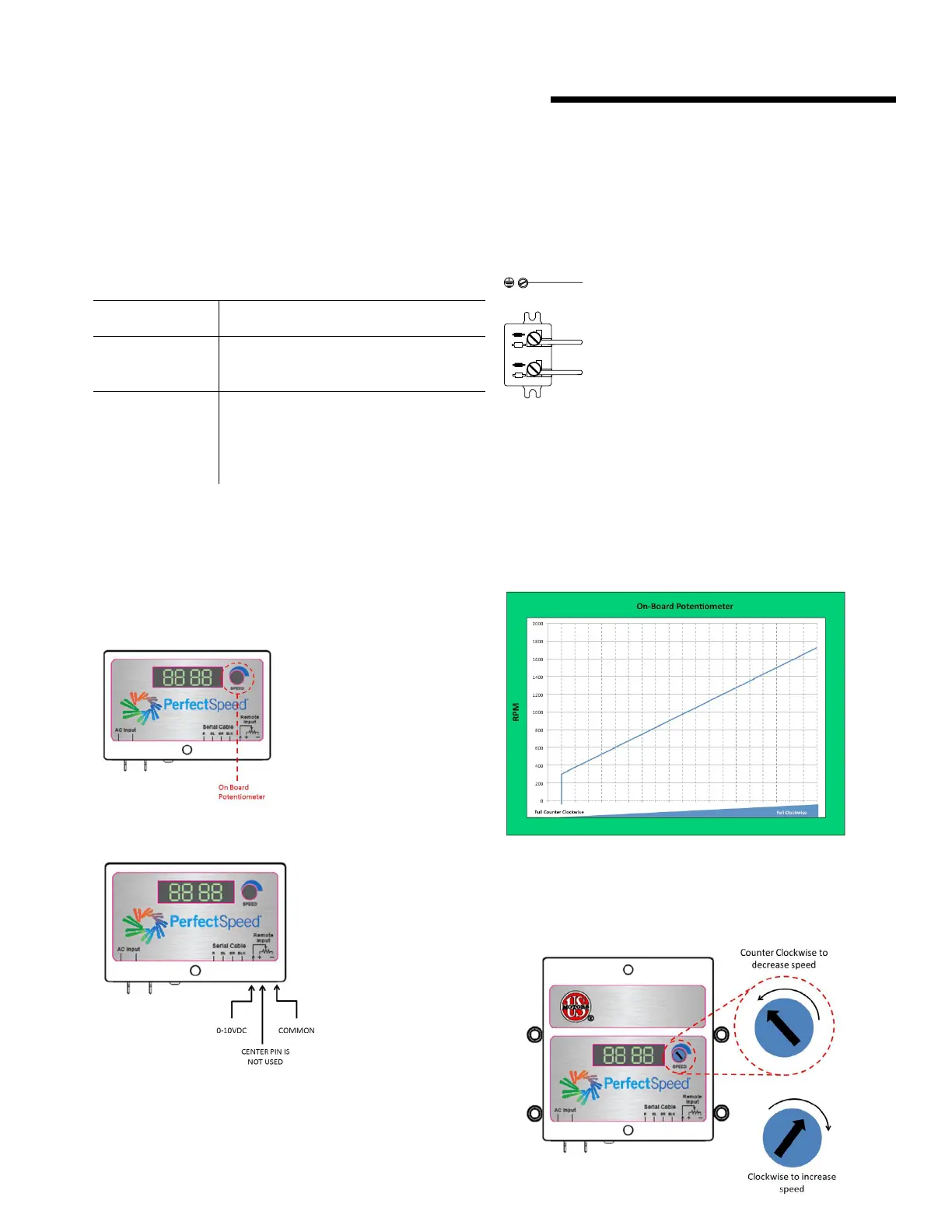
Operating parameters
Speed will change linearly based on the On-Board Potentiometer
or remote 0V to 10V DC signal. The graph below illustrates the
operation of a motor adjusted with the On-Board Potentiometer.
At 0.5V DC signal, the motor will come on at 300 rpm and
ramp linearly to 1800 rpm for ECM series circulators.
Adjusting pump speed (rpm) with on-board potentiometer