Do you have a question about the Armstrong 4280 Series and is the answer not in the manual?
Explanation of symbols used to indicate safety hazards or instructions.
Guidance for safe installation, handling, and operation by trained personnel.
Information on operating temperature limits and necessary precautions.
Advice on the correct methods for lifting and handling the pump set.
Step-by-step instructions for safely priming and starting the pump.
Common pump symptoms and their potential causes for diagnosis.
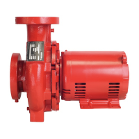
This document provides installation and operating instructions for the Armstrong Series 4280 motor-mounted pump. It is designed to ensure safe and efficient use of the equipment.
The Armstrong Series 4280 is a motor-mounted pump designed for various fluid handling applications. Its primary function is to move liquid through a system, driven by an electric motor. The pump is constructed to be safe and without risk to health and safety when properly installed, operated, and maintained. It is crucial to adhere strictly to the provided instructions for optimal performance and longevity. The pump's design incorporates a casing, impeller, and mechanical seal, all working in conjunction to facilitate fluid transfer. The motor, mounted directly to the pump, provides the necessary power for operation.
The Series 4280 pump is intended for use in both open and closed hydronic systems. For open systems, it should be located as close as practical to the liquid being pumped, with a short, direct suction pipe to minimize resistance and ensure efficient flow. In closed systems, the pump should ideally be installed immediately downstream of the expansion tank/make-up connection, which is the point of zero pressure change, critical for effective pump operation. It's important not to install more than one expansion tank connection into any closed hydronic system.
When installing, ensure adequate space is left above and around the unit for operation, maintenance, service, and inspection of parts. Electric motor-driven pumps should not be located in damp or dusty environments without special protection, and airflow into the motor and/or motor fan must not be obstructed.
The pump should be mounted on a foundation substantial enough to absorb any vibration, ideally weighing approximately 2.5 times the pump's shipping weight. The mounting surface must be level, and shims should be used under the motor feet to compensate for any irregularities in the concrete. Foundation bolts should be tightened evenly.
Piping is a critical aspect of installation. Both suction and discharge pipes must be independently supported near the pump to prevent strain on the pump. All connecting pipework should be accurately located, avoiding any forcing of pipes into position. For suction piping, use short, direct piping one or two times larger than the pump suction nozzle, arranged to eliminate potential air pockets. An eccentric reducer should be used to connect to the suction nozzle. A strainer, three or four times the area of the suction pipe, is recommended to prevent foreign materials from entering the pump, with 5mm diameter perforations being typical.
For discharge piping, a check valve and gate valve should be installed in the line. If an increaser is used to increase the size of the discharge pipe, it should be placed between the check valve and the pump. It's crucial to never connect a pump to piping unless extra care is taken to measure and align the piping flanges well, always starting piping from the pump. Use as few bends as possible, preferably long radius elbows, and ensure the piping exerts no strain on the pump to prevent casing distortion, breakage, or early failure due to misalignment. All connecting pipe flanges must be square to the pipework and parallel to the pump flanges.
Before starting the pump, ensure it turns freely by hand or with mechanical help for larger pumps. All protective guarding must be securely fixed. The pump must be fully primed on start-up; fill the pump casing with liquid and rotate the shaft by hand to remove any trapped air in the impeller. Momentarily energize the motor to check that the rotation corresponds with the directional arrow on the pump casing. To reverse rotation of a three-phase motor, interchange any two power leads. Start the pump with the discharge valve closed and the suction valve open, then gradually open the discharge valve when the motor reaches operating speed. The discharge valve may be "cracked" or open slightly at start-up to help eliminate trapped air. When stopping the pump, close the discharge valve and de-energize the motor. Do not run the pump against a closed discharge valve for an extended period (a few minutes maximum).
Star-Delta motor starters should be fitted with electronic/mechanical interlocks with a timed period of no more than 40 milliseconds when switching from star (starting) to delta (run) connection, allowing the motor to reach full star (starting) speed before switching to delta (run). If the pump is noisy or vibrates on start-up, it may indicate an overstated system head. Calculate the actual pump operating head and compare it to the nameplate value. If the actual head is significantly less, it may be permissible to throttle the discharge isolation valve until the actual operating head equals the nameplate value, which usually resolves noise or vibration.
The Series 4280 pumps are designed for operation without periodic maintenance. However, a systematic inspection at regular intervals will ensure years of trouble-free operation. Key maintenance points include keeping the unit clean, providing the motor with correctly sized overload protection, and keeping moisture, refuse, dust, or other loose particles away from the pump and motor ventilating openings. Avoid operating the unit in overheated surroundings (above 40°C/100°F).
For mechanical seals, no special attention is typically required. If leakage occurs, investigate the cause and replace the seal according to the manufacturer's recommendations, then realign the pump and motor shafts. Do not run the pump unless it is properly filled with water, as mechanical seals require a film of liquid between the faces for proper operation. Mechanical seals may "weep" slightly at start-up; allow the pump to operate for several hours for the seal to "seat" properly before calling for service personnel. Do not use oil, Vaseline, or other petroleum or silicon-based products for seal elastomer lubrication, as this can cause elastomer swelling and seal failure. Recommended: International Products Corp p-80 Rubber Lubricant Emulsion.
The system must be thoroughly cleaned, flushed, drained, and replenished with clean liquid before starting the pump. Welding slag, foreign materials, Stop Leak, cleaning compounds, and improper or excessive water treatment are detrimental to the pump internals and sealing arrangement. Proper operation cannot be guaranteed if these conditions are not adhered to. Under no circumstances should the pump be used for flushing out the system; it should be out of line or bypassed during flushing, in line with CIBSE commissioning code W: 1994.
For motor lubrication, follow the procedures recommended by the motor manufacturer. Many small and medium-sized motors are permanently lubricated and do not require added lubrication. If grease fittings are evident, the motor needs periodic lubrication. Check the lubrication instructions supplied with the motor for the particular frame size indicated on the motor nameplate.
Regular checks should be performed before operation: ensure the pump is primed, rotation is correct, lubrication is adequate, pipework is properly supported, voltage supply is correct, overload protection is working, the system is clean, and the area around the pump is clean.
The permissible TDS (Total Dissolved Solids) levels are: SSIC Vs C - 2000ppm max, and SSIC Vs SSIC - 4000ppm max. If water exceeds these levels, corrosion or fouling may occur, leading to seal failures. Maintaining water quality with a proper water treatment program is necessary.
The warranty does not cover damages resulting from failure to observe these precautions. Refer to Armstrong General Terms and Warranty sheet for full information.
| Series | 4280 |
|---|---|
| Construction | Close-coupled |
| Impeller Type | Closed |
| Power Source | Electric |
| Shaft Seal | Mechanical Seal |
| Weight | Varies by model |
| Material | Cast Iron |
| Inlet Size | 4 inch |
| Outlet Size | 4 inch |
| Operating Temperature | Up to 250°F |