Do you have a question about the Armstrong Design Envelope 4302 and is the answer not in the manual?
Procedure for safely handling the pumping units to prevent damage.
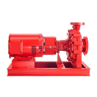
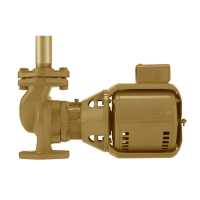
Guidelines for physical installation of the pump unit.
Recommendations for pump piping layout and installation.
Factory alignment verification and procedures.
Procedure for priming and starting the pump correctly.
Routine inspection, care, and lubrication requirements.
Importance of system cleanliness before pump operation.
Operation and locking mechanisms for the discharge valve.
Operation and locking mechanisms for the suction valve.
Statement of conformity with relevant EU directives.
Guidelines for mechanical installation, including access and orientation.
Standard enclosure rating and options for dusty/wet environments.
Recommended ambient temperature limits for inverter operation.
Causes and safety considerations for earth leakage current.
Start/stop limits and preferred methods for ivs Sensorless Pumps.
Built-in motor/inverter protection features.
Details on required supply voltage, tools, and cable entry sizes.
Maximum cable cross-section for mains and control cables.
Step-by-step guide for connecting the main power supply to the inverter.
Overview of terminal blocks used for control connections.
Detailed description of X101 terminal functions for control signals.
Function of X102 terminals for pump running identification.
Examples of common control configurations for ivs Sensorless pumps.
Using BMS or potentiometer for constant curve speed control.
Wiring arrangement for remote LCP keypad.
Overview of programming, monitoring, and diagnostic features.
Functions and operation of the Local Control Panel (LCP).
Description of the LCD display and its information output.
Explanation of the indicator lights (LEDs) on the control panel.
Functions of the control keys for navigation and operation.
Different display modes and how to select them.
Accessing parameters via quick menu and full menu modes.
How to select parameter groups and change data values.
Introduction to sensorless control concept and benefits.
Default mode using a control curve for pressure control.
Parameters for configuring quadratic pressure control.
Configuring the pump to maintain constant system pressure.
Parameters for constant pressure control settings.
Configuring for linear reduction in head with reducing flow.
Parameters for proportional pressure control.
Configuring for closed-loop control using external feedback signals.
Detailed descriptions of parameter groups and their functions.
Steps to change to external sensor control mode.
Steps to change to open loop (BAS) control mode.
Steps to change to sensorless control mode.
Information on warnings, alarms, and their indications.
Description of internal LEDs for status indication.
Troubleshooting flow chart for issues when keypad is available.
Troubleshooting flow chart for issues when keypad is unavailable.
Detailed descriptions of various fault messages and their causes.
Overview of integrated control features.
Causes and safety considerations for ground leakage current.
Guidelines for pump start/stop frequency and maintenance isolation.
Requirements for supply fusing and grounding, including IT mains.
Configuration and wiring of relays for running and alarm status.
Diagram showing all electrical and control connections.
Procedure for accessing control terminals and their functions.
Examples of common connection configurations for ivs Sensorless pumps.
| Brand | Armstrong |
|---|---|
| Model | Design Envelope 4302 |
| Category | Water Pump |
| Language | English |