installation &
operating instructions
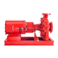
Design Envelope 4302 ivs and 4382 ivs vertical
in-line pumping unit with integrated controls
44
Alarms that are trip-locked o er additional protection, means
that the mains supply must be switched o before the alarm
can be reset. After being switched back on, the inverter is no
longer blocked and may be reset as described above once the
cause has been rectifi ed.
Alarms that are not trip-locked can also be reset using the
automatic reset function in
Par
. 14-20 reset mode (Warn-
ing: automatic wake-up is possible!). If a warning and alarm
is marked against a code in the table on the following page,
this means that either a warning occurs before an alarm, or
it can be specifi ed whether it is a warning or an alarm that is
to be displayed for a given fault. This is possible, for instance,
in
Par
. 1-90 Motor Thermal Protection. After an alarm or trip,
the motor carries on coasting, and the alarm and warning
fl ash on the inverter. Once the problem has been rectifi ed,
only the alarm continues fl ashing.
14.1 fault messages
warning 1 , 10 Volts low:
The 10v voltage from terminal 50 on the control card is below
10v. Remove some of the load from terminal 50, as the 10v
supply is over-loaded. Max. 15 mA or minimum 590 .
warning/alarm 2, Live zero error:
The signal on terminal 53 or 54 is less than 50% of the value
set in
Par.
6-10 Terminal 53 Low Voltage,
Par.
6-12 Terminal
53 Low Current,
Par.
6-20 Terminal 54 Low Voltage, or
Par.
6-22 Terminal 54 Low Current respectively.
warning/alarm 3 , No motor:
No motor has been connected to the output of the inverter.
warning/alarm 4 , Mains phase loss:
A phase is missing on the supply side, or the mains voltage
imbalance is too high. This message also appears in case of
a fault in the input rectifi er on the inverter. Check the supply
voltage and supply currents to the inverter.
warning 5, dc link voltage high:
The intermediate circuit voltage (dc) is higher than the over-
voltage limit of the control system. The inverter is still active.
warning 6, dc link voltage low:
The intermediate circuit voltage (dc) is below the under volt-
age limit of the control system. The inverter is still active.
warning/alarm 7, dc over voltage:
If the intermediate circuit voltage exceeds the limit, the
inverter trips after a time.
warning/alarm 8, dc under voltage:
If the intermediate circuit voltage (dc) drops below the “volt-
age warning low” limit, the inverter checks if 24v back-up
supply is connected. If no 24v backup supply is connected,
the inverter trips after a given time depending on the unit.
warning/alarm 9, Inverter overloaded:
The inverter is about to cut out because of an overload (too
high current for too long). The counter for electronic, thermal
inverter protection gives a warning at 98% and trips at 100%,
while giving an alarm. You cannot reset the inverter until the
counter is below 90%.The fault is that the inverter is over-
loaded by more than nominal current for too long.
warning/alarm 10
, Motor etr over temperature:
According to the electronic thermal protection (etr), the mo-
tor is too hot. You can choose if you want the inverter to give
a warning or an alarm when the counter reaches 100% in Par.
1-90 Motor Thermal Protection. The fault is that the motor is
overloaded by more than nominal current for too long. Check
that the motor Par. 1-24 Motor Current is set correctly.
warning/alarm 11
, Motor thermistor over temp:
The thermistor or the thermistor connection is disconnected.
You can choose if you want the inverter to give a warning or
an alarm in Par. 1-90 Motor Thermal Protection. Check that
the thermistor is connected correctly between terminal 53 or
54 (analog voltage input) and terminal 50 (+ 10 Volts supply),
or between terminal 18 or 19 (digital input pnp only) and ter-
minal 50. If a kty sensor is used, check for correct connection
between terminal 54 and 55.
warning/alarm 12
, Torque limit:
The torque is higher than the value in Par. 4-16 Torque Limit
Motor Mode (in motor operation) or the torque is higher
than the value in Par.4-17 Torque Limit Generator Mode (in
regenerative operation).
warning/alarm 13
, Over Current:
The inverter peak current limit (approx. 200% o f t h e r a t e d
current) is exceeded. The warning will last approx. 8-12
sec., then the inverter trips and issues an alarm. Turn o the
inverter and check if the motor shaft can be turned and if the
motor size matches the inverter.
alarm 14
, Earth fault:
There is a discharge from the output phases to earth, either
in the cable between the inverter and the motor or in the mo-
tor itself. Turn o the inverter and remove the earth fault.
alarm 15
, In-complete hardware:
A fi tted option is not handled by the present control board
(hardware or software).
 Loading...