installation &
operating instructions
Design Envelope 4302 ivs and 4382 ivs vertical
in-line pumping unit with integrated controls
36
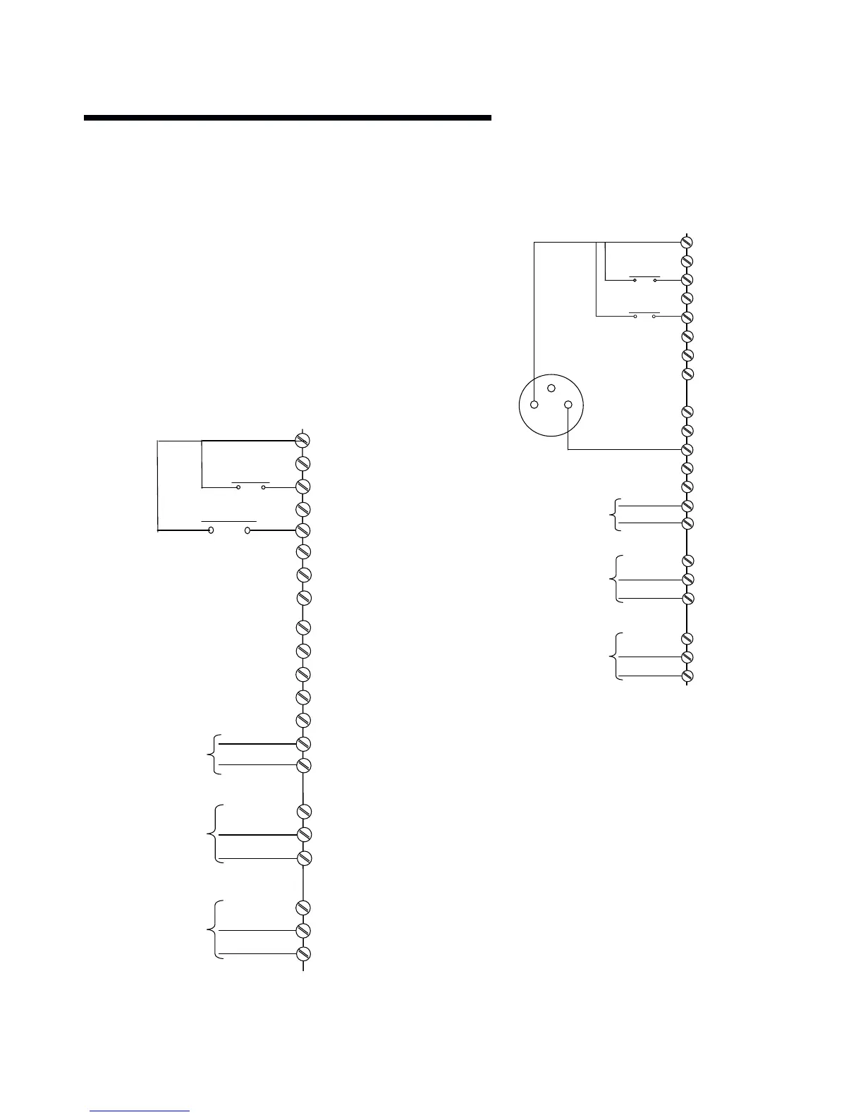
11.8.3 connection examples
ivs Sensorless pumps can be confi gured in four main ways:
i Sensorless
ii Closed loop – with feedback sensor
iii Constant curve mode – Potentiometer Control
iv Constant curve mode – bms signal
iv.i Full speed override
i sensorless
ivs sensorless pumps are factory confi gured to be
connected as shown below.
ii closed loop – with sensor feedback
To control the pump based on a 4-20mA feedback signal
from a sensor use the following connection.
12 (+24v )
20 (0v )
18 (d in)
Start Signal
Output Frequency
4-20mA Analogue Out
Running Output
Alarm Output
19 (
(
d
d
in
in
)
)
50 (10v)
53 (Ain)
54 (Ain)
55 (0v )
42 (Aout)
39 (Aout)
2 (r1 n/o)
3 (r1 n/c)
1 (r1 com)
5 (R2 N/ O)
6 (R2 N/C)
4 (R2 COM)
29 (d in)
32 (d in)
33 (d in)
27
24v
12 (+24v )
20 (0v )
18 (d in)
Start Signal
Output Fr equency
4-20mA Analog ue Out
Running Output
Alarm Output
19 (d in)
27 (d in)
29 (d in)
32 (d in)
33 (d in)
50 (10v)
53 (Ain)
54 (Ain)
55 (0v )
42 (Aout)
39 (Aout)
2 (r1 n/o)
3 (r1 n/c)
1 (r1 com)
5 (R2 N/O)
6 (R2 N/C)
4 (R2 COM)
Pressure Sensor
(0-10 bar / 4 -20ma)
Feedback from Sensor
4-20mA - Input t54
Power Supply (24 vdc)
for sensor t13=24v
Low Water
Cutout
Low Water
Cutout


 To Next Page