installation &
operating instructions
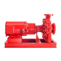
Design Envelope 4302 ivs and 4382 ivs vertical
in-line pumping unit with integrated controls
33
11.7 relay connections
The relays on the ivs are confi gured as follows:
relay 1 – running
• Terminal 01: Common
• Terminal 02: Normal open 240v ac
• Terminal 03: Normal closed 240v ac
relay 2 – alarm
• Terminal 04: Common
• Terminal 05: Normal open 400v ac
• Terminal 06: Normal closed 240v ac
fig. 7 Relay contact details
04
05
06
01
02
03
240v ac, 2a
400v ac, 2a
240v ac, 2a
Relay 1
Relay 2
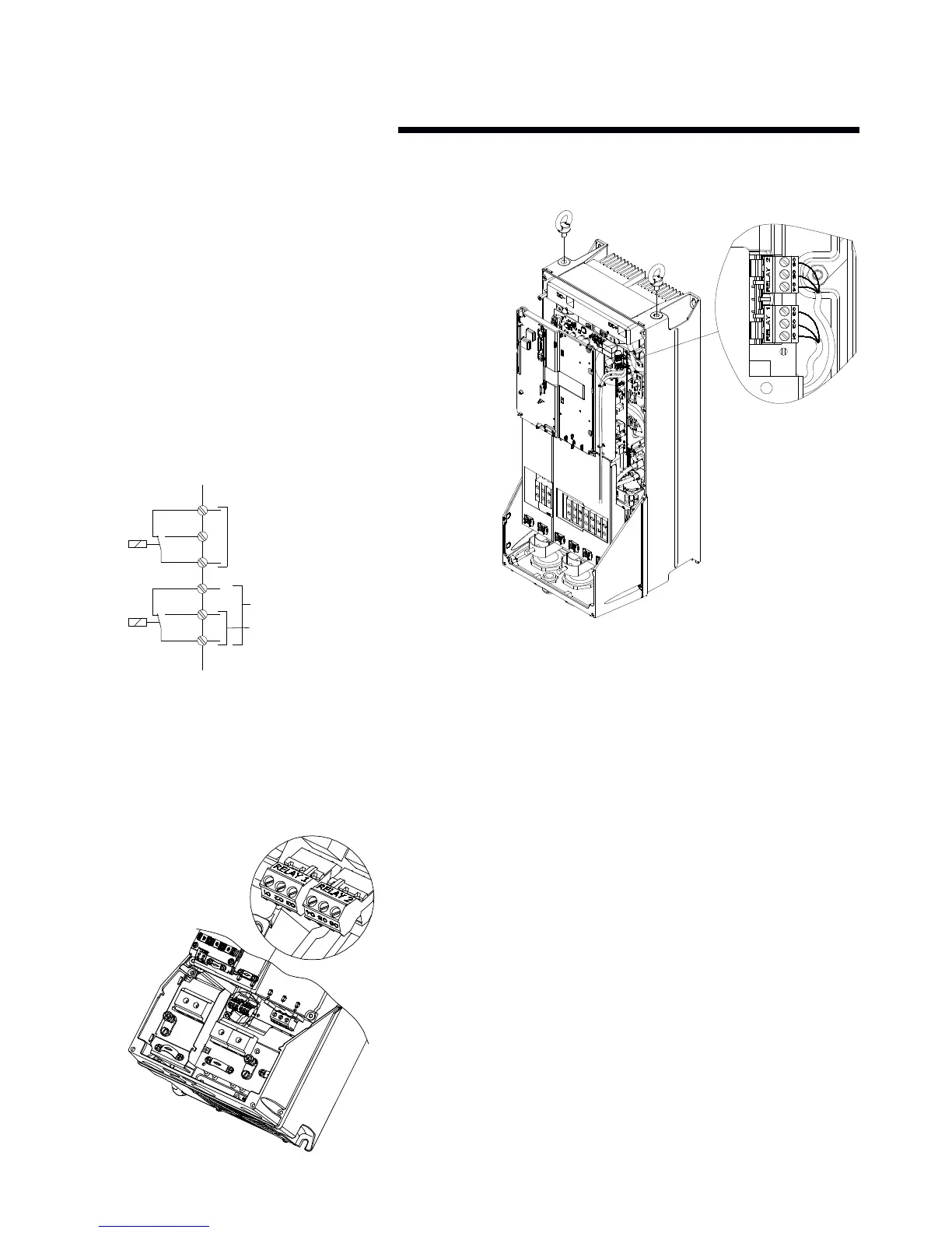
The following illustrations identify the location of the relays
within specifi c inverter sizes:
The illustrations in fi gures 6, 7 and 8 identify the location of
the relays within specifi c inverter sizes:
fig. 8 Relay connection: terminals for a5, b1 and b2 units
fig. 9 Relay connection terminals for c1 and c2 units
 Loading...