installation &
operating instructions
Design Envelope 4302 ivs and 4382 ivs vertical
in-line pumping unit with integrated controls
4
1.0 uncrating
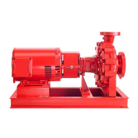
Armstrong dualArm Design Envelope 4302 ivs and 4 3 8 2 i v s
in-line pumps are thoroughly inspected before shipment to
assure they meet with your order requirements. After remov-
ing the pump from the crate, make sure the equipment is in
good order and that all components are received as called
for on the packing list. Any shortages or damage should be
reported immediately. Use extreme care in handling the unit,
placing slings carefully so that stress will not be imposed on
the integrated controls, pump or motor. Never place cable
slings around the pump shaft or integrated controls. The
eye bolts or lifting lugs on the motor are intended for lifting
only the motor and not the complete unit.
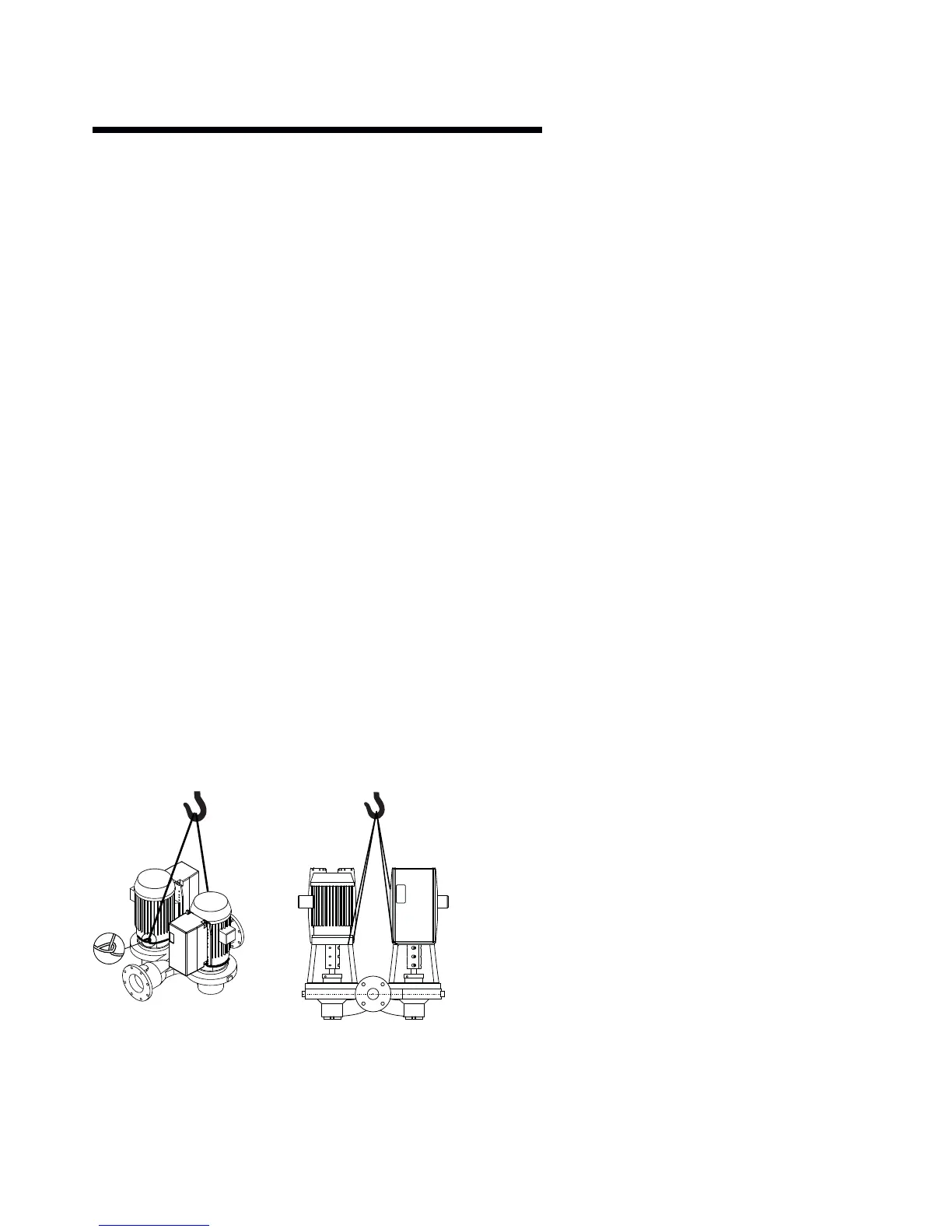
1.1 handling 4302 ivs & 4382 ivs units
Series 4302 ivs and 4382 ivs dualArm units are handled in a
similar manner to the normal dualArm units. Extra care is
required to ensure the integrated controls do not get dam-
aged during lifting and installation. Remove the coupling
guards and insert lifting straps through each pump/motor
pedestal on the inner side of each coupling. As the lifting
device is engaged (Using a spacer bar if necessary) and the
straps tighten ensure no part of the strapping is touching any
part of the control or motor fan cover. Lift the pumping unit
carefully from the pallet in this manner and allow the unit to
stand upright on a fl at surface and re-position the straps, if
necessary, to ensure safe and damage free transportation
into the pipe installation
2.0 installation
2.1 mechanical installation
2.1.1 location
Locate the unit as close as practical to the liquid being
pumped, with a short, direct suction pipe. Ensure adequate
space is left above and around the unit for operation, mainte-
nance, service and inspection of parts.
Electric motor driven pumps should not be located in damp
or dusty location without special protection.
2.1.2 storage
Pumps not immediately placed into service, or removed
from service and stored, must be properly prepared to
prevent rusting.
Rotate the shaft periodically to keep rotating element free.
For long term storage, the pump must be placed in a vertical
position in a dry environment.
Internal rusting can be prevented by removing the plugs at
the top and bottom of the casing and drain or air blow out all
water to prevent rust build up or the possibility of freezing.
Be sure to reinstall the plugs when the unit is made opera-
tional. Rustproofi ng or packing the casing with moisture
absorbing material and covering the fl anges is acceptable.
When returning to service be sure to remove the drying
agent from the pump.
2.1.3 installation
The most important consideration when installing a Series
4302 ivs and 4382 ivs pumping unit is to make sure the pump
is free to ‘fl oat’ with expansion and contraction of the piping.
Recommended arrangements are:
• Supported from the ceiling by pipe hangers
(see fi g. 2.1 on page 9)
• Pipe supported at the ceiling, with the dualArm free-
standing and mounted with an Armstrong Suction Guide
& Flo-Trex valve. (See fi gs. 2.2 & 2.3 on page 9)
• Piping supported at ceiling with additional fl o o r m o u n t e d
supports under Armstrong Suction Guide and Flo-Trex
valve (see fi g. 2.4 on page 9)
• Floor mounted saddle supports (see fi g. 2.5 on page 10)
• Where required, additional fl oor support may be obtained
as shown in fi g. 2.5. N ote that the p um p must not be rigidly
attached either to the plate or to the block. Leave a V"
(3mm) gap between pump and base. The piping must be
4382 ivs 4302 ivs
 Loading...