116
i
*
.
*
"
^.
•
*
wC^
'•
1
*'
*
-w
.
• H
k
\j-
f
'
'
'I K
\I
«
n
-
vl
"
•
•
'
*
*
H
•TV
"•
•'.••-
1\
I \
-
-
'
S I
*
1
•
A
*
™ 1
-
:
4 'A
••
•
1
M
-
\ *H
•*-•*
V
•
*
'
*
M m
•1-
.
*
\
.••*
V
I
• v M~
•.'
V
•
H I
•;;.!.•
•
V
;
,H 1
-
:
*
v
:
\'
'->"'*
I
•*
I
.
*
-
\
'
•
I
1
-
•
A
V
'
I
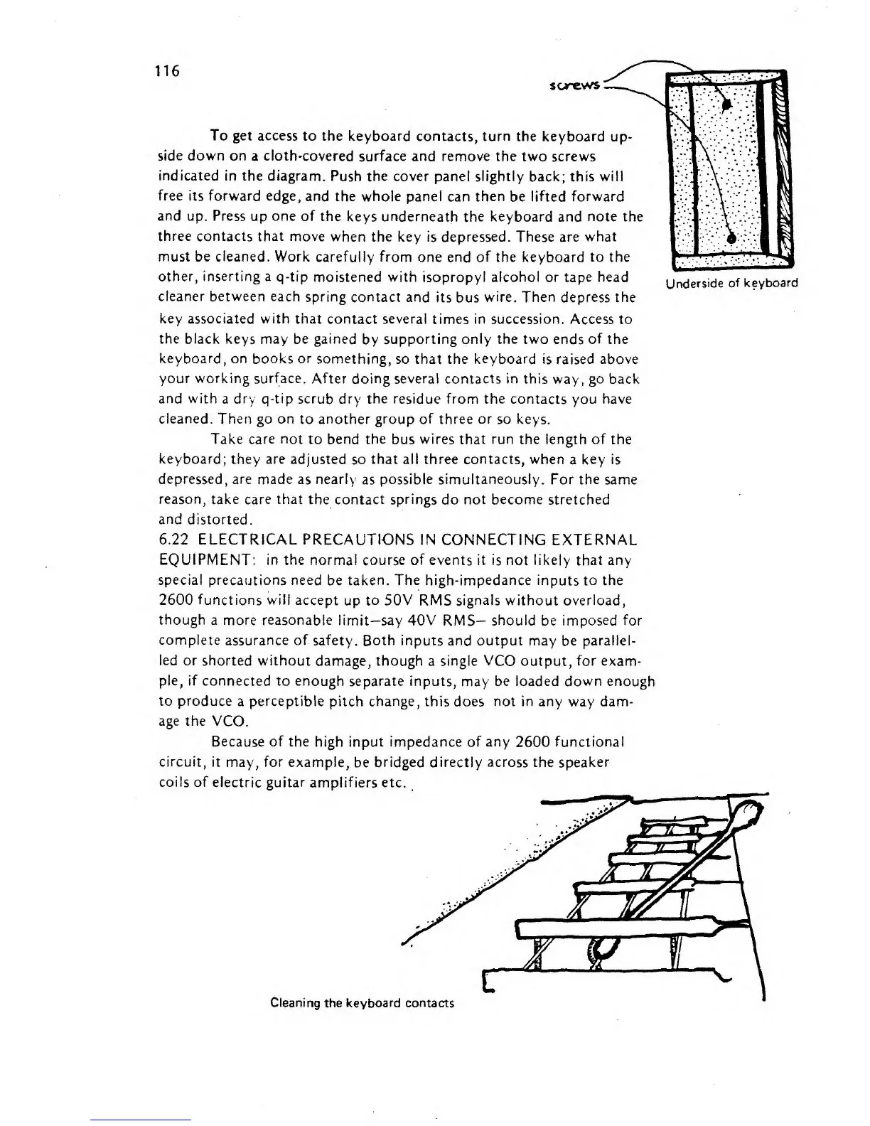
To get access
to
the keyboard
contacts, turn the keyboard
up-
side
down
on
a
cloth-covered
surface and remove
the two screws
indicated in
the
diagram.
Push the cover panel slightly
back; this
will
free
its forward edge,
and
the
whole panel
can then be lifted forward
and up.
Press up
one
of
the
keys underneath
the
keyboard
and
note
the
three
contacts that move when
the key
is
depressed. These are
what
must be cleaned. Work
carefully from one
end of
the keyboard to
the
other,
inserting a
q-tip
moistened
with
isopropyl alcohol or tape head
Underside
of
keyboard
cleaner
between each spring
contact and
its bus
wire.
Then depress
the
key associated with
that contact several
times
in succession.
Access to
the black
keys may be gained
by
supporting only the two
ends
of
the
keyboard, on
books
or
something, so that the keyboard is raised above
your working surface.
After doing several
contacts
in
this way,
go
back
and with
a
dry q-tip
scrub dry
the
residue from the contacts
you
have
cleaned.
Then
go on
to another
group
of three
or
so
keys.
Take care not
to
bend the
bus
wires that run
the
length
of the
keyboard;
they
^re
adjusted
so
that
all
three
contacts, when
a
key is
depressed, are made as nearly
as
possible simultaneously.
For the same
reason, take care
that
the
contact springs
do
not become
stretched
and
distorted.
6.22 ELECTRICAL PRECAUTIONS IN
CONNECTING EXTERNAL
EQUIPMENT:
in the normal course
of
events it is
not
likely
that any
special
precautions need be
taken. The
high-impedance
inputs
to the
2600
functions
will
accept
up
to 50V RMS signals without overload,
though a more reasonable
limit—say 40V RMS— should
be
imposed for
complete assurance of
safety.
Both
inputs
and
output
may be
parallel-
led or
shorted
without
damage, though
a single
VCO
output, for exam-
ple, if connected
to
enough
separate inputs,
may be
loaded down enough
to produce
a
perceptible
pitch
change, this does not in any
way
dam-
age the
VCO.
Because
of the
high input impedance
of
any
2600 functional
circuit,
it may, for example,
be
bridged directly across the
speaker
coils of
electric
guitar
amplifiers etc.
Cleaning
the keyboard contacts