19
control
path
auAi*
ts^rt*! p**h
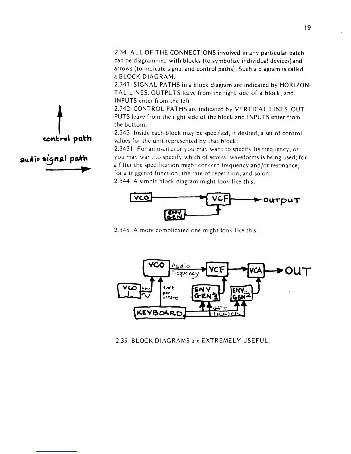
2.34 ALL
OF THE
CONNECTIONS involved in
any particular patch
can be
diagrammed
with
blocks
(to symbolize individual devices)and
arrows (to
indicate
signal and
control paths).
Such
a diagram
is called
a
BLOCK
DIAGRAM.
2.341
SIGNAL
PATHS
in a block diagram are indicated
by HORIZON-
TAL
LINES.
OUTPUTS
leave from
the
right
side of
a block,
and
INPUTS enter
from
the left.
2.342
CONTROL-PATHS are
indicated
by VERTICAL
LINES.
OUT-
PUTS leave from
the
right
side of
the block and INPUTS
enter from
the
bottom.
2.343 Inside
each
block may be specified, if
desired, a set of control
values
for
the
unit represented
by that
block:
2.3431 For
an oscillator
you
may
want
to
specify its frequency, or
you may
want
to
specify which of several
waveforms
is
being
used;
for
a
filter
the
specification
might concern frequency
and/or resonance;
for
a
triggered
function, the
rate
of repetition,
and so on.
2.344
A
simple
block
diagram might look
like
this.
OUTpuT
2.345
A more complicated one
might look
like this.
OUT
2.35
BLOCK DIAGRAMS
are
EXTREMELY USEFUL