Do you have a question about the ARP 2600 and is the answer not in the manual?
Emphasizes careful and frequent reading of the manual for optimal use.
Warns against adjusting recessed calibration points without proper familiarity.
Strict warning against opening the unit to avoid voiding the warranty.
Explains how acoustical waveforms are generated and modified electronically.
Clarifies the distinction between physical waveform properties and perceived sound attributes.
Explains how changes in waveform shape affect the perceived timbre or tone color of a sound.
Lists and briefly describes the basic periodic waveforms generated by oscillators.
Explains the characteristics of white noise and pink noise.
Categorizes frequencies relative to human hearing and their properties.
Relates the shape of an event to its envelope or contour characteristics.
Describes the process of adding waveforms together, akin to additive synthesis.
Details the design of synthesizers with voltage-controlled oscillators, filters, and amplifiers.
Explains the gate, trigger, and control voltage signals generated by the keyboard.
Explains the methods used to connect synthesizer components, like patch cords or matrix boards.
Explains the conventions for drawing signal paths and control paths in block diagrams.
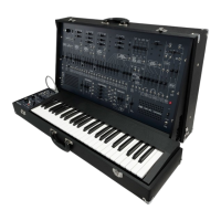
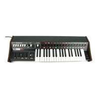
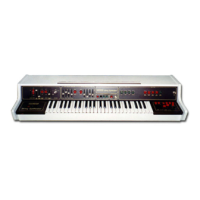
Describes the physical attributes of the ARP 2600, highlighting its portability and integrated nature.
Details the reliability, robust build, and extensive flexibility of the ARP 2600.
Highlights features beneficial for live performance and educational purposes.
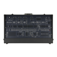
Guides the user through identifying the main controls on the synthesizer panel.
Categorizes and describes the various input and output jacks available on the panel.
Explains the function of slider controls, particularly attenuators and their role.
Details keyboard controls and highlights the system's prewired connections.
Illustrates prewired connections involving the mixer and voltage-controlled filter.
Offers advice on how to approach experimentation to understand synthesizer functions effectively.
Identifies the five primary voltage-controlled functions: three VCOs, VCF, and VCA.
Explains the operating ranges, manual controls, and frequency control inputs for each VCO.
Details the sawtooth and square wave outputs from VCO-1.
Describes how the cutoff frequency (Fc) is controlled manually and by voltage.
Details the function of the resonance (Q) control and its effect on the filter's response.
Differentiates between linear and exponential sensitivity for VCA control voltage inputs.
Explains the output characteristics of the noise generator, including bandwidth and signal levels.
Explains how gate signals control envelope generator output and maximum voltage.
Describes the attack, decay, sustain, and release parameters of the ADSR generator.
Details how the S/H circuit operates with signal and sample command inputs.
Details the risetime, ripple, and use of the envelope follower.
Explains the Tone Interval control for adjusting pitch intervals across the keyboard.
Compares the effects of AC and DC coupling on ring modulator inputs and outputs.
Explains the phase inversion and summing capabilities of the inverting processors.
Details how the lag processor slows down sudden changes in input voltage.
Describes the microphone preamp's gain stages and the electronic switch's bidirectional nature.
Explains the internal clock oscillator and the mixer/panpot signal routing.
Outlines two key principles for synthesizer use: no damage potential and usefulness of connections.
Discusses prewired connections and the importance of setting unused attenuators.
Defines abbreviations used in block diagrams and general path conventions.
Details the core signal flow of the classic patch, focusing on filtering and amplification.
Demonstrates how adjusting pulse width affects the waveform and sound.
Highlights the sine wave's purity and its role as a building block for other waveforms.
Explains how lowering the cutoff frequency affects the noise signal by attenuating high frequencies.
Discusses the harmonic content of square, sine, and pulse waves and their timbre.
Compares manual gain control with voltage-controlled amplitude modulation.
Details connecting VCO2 sine output to the VCA's linear control input for amplitude modulation.
Recommends substituting VCOs for the noise generator to explore modulation.
Explores AM effects by varying signal and control frequencies and levels.
Details using the AR envelope generator with manual start and release controls to shape VCA output.
Shows how the VCF can create audible events when controlled by an ADSR envelope.
Describes the creation of frequency modulation effects by using one oscillator to control another.
Guides users to explore the ring modulator's interaction with VCF and VCA.
Emphasizes the importance of making notes and understanding how effects are generated.
Details variations of the Sample/Hold and Internal Clock patch for sequence generation.
Describes a patch designed to produce intermittent sound, potentially for percussion.
Explores frequency modulation effects and their cataloging.
Examines the difference between AC and DC coupling with the Ring Modulator.
Discusses modulating timbre or harmonics using the VCF with various inputs.
Details a patch for creating a 'footsteps' sound effect through critical control settings.
Illustrates a basic patch using an external source to control synthesizer functions via envelope follower.
Describes using external tape echo and graphic equalizers for signal processing.
Covers routine cleaning, protection from environmental factors, and general care.
Explains how to use the semi-fixed trimmers for calibration adjustments.
Specifies initial settings for keyboard and panel controls during alignment.
Provides step-by-step instructions for calibrating the frequency of each VCO.
Explains how to adjust the VCF's output offset trimmer for minimum pitch change.
Explains how to adjust the VCA for minimum high-frequency signal through speakers.
Guides the user through adjusting the POS NULL and NEG NULL trimmers for minimum signal.
Warns against disassembling the unit and adjusting fixed trimmers to avoid voiding warranty.
Explains the process for cleaning keyboard contacts to ensure steady control voltage.
| Type | Analog Semi-Modular Synthesizer |
|---|---|
| Oscillators | 3 VCOs (Voltage Controlled Oscillators) |
| Polyphony | Monophonic |
| Effects | Spring Reverb |
| Year Released | 1971 |
| Manufacturer | ARP Instruments, Inc. |
| Filter | 24 dB/oct low-pass filter |
| Envelopes | ADSR |
| LFO | 1 LFO |
| Inputs/Outputs | CV/Gate, Audio Input/Output |
| Weight | Approx. 18 kg (40 lbs) |